


THEORY OF OPERATION
E-4 E-4
VANTAGE® 500
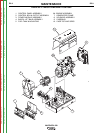
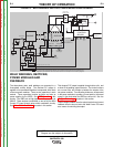
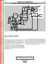
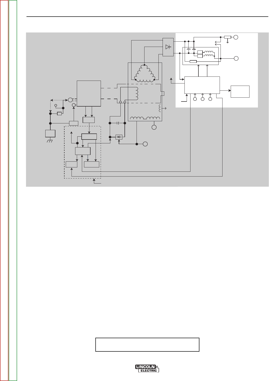
FIGURE E.4 - POWER MODULES AND WELD CONTROL BOARD
WELD CONTROL BOARD
The 80 VDC derived from the filter capacitors on the
Power Modules, supplies various regulated DC volt-
ages to operate the Weld Control PC board circuitry. It
also supplies two regulated DC voltages to operate the
IGBT driver circuitry on the two Power Modules.
The Weld Control PC board monitors the operator con-
trols (arc control, output, and process/range selector).
It compares these commands to the current and voltage
feedback information it receives from the shunt and out-
put terminal circuits.
The circuitry on the Weld Control PC board determines
how the output should be controlled to optimize welding
results, and it sends the correct PWM signals to the
IGBT driver circuits. The Weld Control PC board also
commands the thermal light and the voltmeter and
ammeter (some items may be optional).
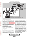
NOTE: Unshaded areas of Block Logic
Diagram are the subject of discussion
ENGINE ROTOR
STATOR
AUXILIARY WINDINGS
W
E
L
D
W
I
N
D
I
G
MECHANICAL
ROTATION
ALTERNATOR
OUTPUT
CONTROL
MODE
SELECT
SWITCH
SLIP
RINGS
ARC
CONTROL
WELD
CONTROL
BOARD
VOLTMETER
AMMETER
42 VAC and 120VAC
to 14 Pin Amphenol
for Wire Feeder
(No 120 VAC on EURO Models)
THREE-PHASE
RECTIFIER
++
++
____
TO WELD
CONTROL
BOARD
__
START
BUTTON
+
BATTERY
ON
STARTER
+12 VDC
RUN
ENGINE
SENSORS
OIL
PRESSURE
WATER
TEMP.
PERIPHERAL
PCB
PULL
COIL
PCB
+12 VDC
RUN
FUEL
SOLENOID
PULL
HOLD
FLASHING
IDLER
SOLENOID
LOW IDLER SIGNAL (TO SUPPLY PULL VOLTS)
HOLD VOLTS FROM CONTROL PCB
25•
(COLD)
120 VAC
RECEPTACLES
(Not on EURO Machnes)
AC RECEPTACLES
Various combinations of
1Ø and 3Ø Outputs.
See Techincal Specs.
IGBT
IGBT
CHOKE
R4-50•
2-POWER MODULES
SHUNT
TO
CONTROL
PCB
AUX. POWER
USE SENSING
+12VDC
RUN
80 VDC
PWM
SIGNAL
PWM
SIGNAL
120VAC
160VDC
120VAC
PULL
RUN/STOP
SWITCH
* On some codes the Peripheral Board, Pull Coil Board, Idler Solenoid & Fuel Solenoid are
replaced by an Electronic Governor Control module and components. See Wiring Diagram.
Return to Section TOC Return to Section TOC Return to Section TOC Return to Section TOC
Return to Master TOC Return to Master TOC Return to Master TOC Return to Master TOC