


A-4
INSTALLATION
INVERTEC V250-S
A-4
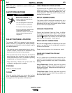
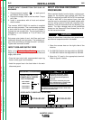
POWER INPUT CONNECTION FOR 50/60 HZ
MACHINES
1. Connect terminal marked to earth ground
per National Electric Code.
2. Connect the supply lines to the line switch. Torque
to 3.0 Nm.
3. Install in accordance with all local and national
electric codes.
The Invertec V250-S 50/60 Hz machine is supplied
with one cord connector. The cord connector provides
a strain relief for the input power cord as it passes it
through the rear access hole. The cord connector is
designed for a cord diameter of 7.9 to 27.2mm (.310
to 1.070 in).
Strip away outer jacket of cord, trim fillers and insert
conductors through cord connector. The jacketed por-
tion of the cord must go through the cord connector.
Tighten both connector screws.
INPUT FUSE AND SUPPLY WIRE
Refer to the
Technical Specifications
page at the
beginning of this chapter for the proper fuse sizes and
supply cable sizes.
• Fuse the input circuit with recommended super lag
fuses or delay type circuit breakers.
• Install the proper fuse in the fuse holder in the main
disconnect panel.
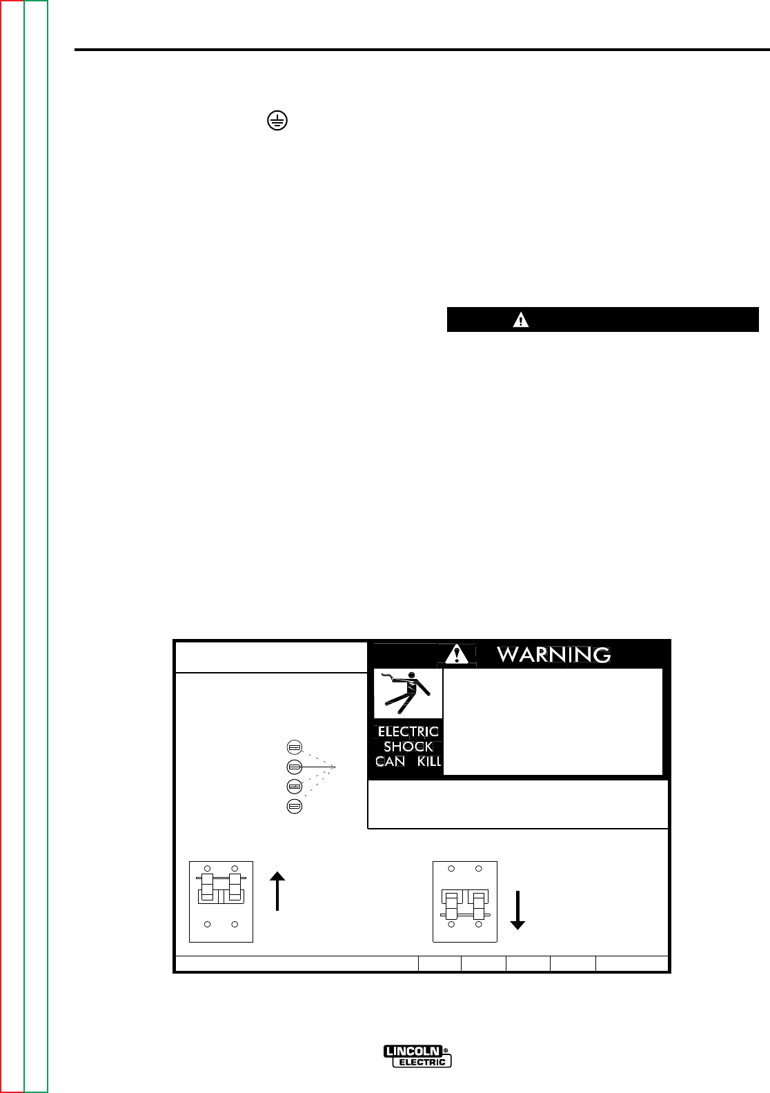
INPUT VOLTAGE RECONNECT
PROCEDURE
When received directly from the factory, units are con-
nected for the highest input voltage, 440 VAC for
50/60 Hz machines and 460 VAC for 60 Hz machines.
If 440 or 460 VAC is the desired input, then the
machine may be connected to the power system with-
out any setup required inside the reconnect door.
However, verify the connection with the following pro-
cedure. For other voltages refer to the instructions
located on the Reconnect Panel Access Door or fol-
low the instructions below.
Failure to follow these instructions can cause immedi-
ate failure of components within the welder.
------------------------------------------------------------------------
1. Open the access door on the right side of the
machine.
2. For 200-230: Position the large switch to 200-230.
For 380-460: Position the large switch to 380-460.
3. Move the “A” lead to the appropriate terminal.
Refer to figure A.1 below.
Return to Section TOC Return to Section TOC Return to Section TOC Return to Section TOC
Return to Master TOC Return to Master TOC Return to Master TOC Return to Master TOC
THE LINCOLN ELECTRIC CO. CLEVELAND, OHIO U.S.A.
.
.
.
.
Do not touch electrically live parts.
Only qualified persons should install,
use or service this equipment.
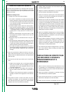
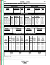
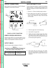
RECONNECT PROCEDURE
1. BE SURE POWER SWITCH IS OFF.
200-208V
220-230V
380-415V
440-460V
'A'
INPUT VOLTAGE RANGE.
removed.
Do not operate with wraparound
inspecting or servicing machine.
Disconnect input power before
IF MACHINE CEASES TO OPERATE (NO METER, NO FAN)
2. CONNECT LEAD 'A' TO DESIRED
3. POSITION SWITCH TO DESIRED INPUT VOLTAGE RANGE.
S21230
AND THERE IS NO OTHER KNOWN FAILURE: CHECK FUSE;
VOLTAGE=380-460V
VOLTAGE=200-230V
REPLACE WITH SPECIFIED FUSE.
A
CAUTION
Figure A.1 Input Voltage Reconnect Instructions