


Return to Section TOC Return to Section TOC Return to Section TOC Return to Section TOC
Return to Master TOC Return to Master TOC Return to Master TOC Return to Master TOC
F-75
TROUBLESHOOTING & REPAIR
F-75
INVERTEC V250-S
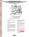
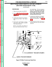
21. With the 3/4” wrench assemble the
positive output lead to the positive
output terminal.
Take note of the by-pass connec-
tion on the positive output terminal.
22. Reassemble the shunt assembly to
the negative output terminal. Take
note of the by-pass connection on
the negative terminal. Clear leads
and install any necessary cable
ties.
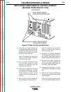
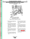
23. Connect the two thermostat leads.
24. Connect the shunt sensing leads to
the control board (plug J4).
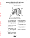
25. Connect primary leads #201, #204,
#205 and #208 to the power board.
Be sure leads #204 and #205 are
routed through the current trans-
former (T3) in the correct man-
ner.
Secure leads with cable ties.
26. Clear all leads and secure for case
wrap-around assembly.
MAIN TRANSFORMER REMOVAL AND REPLACEMENT
(MACHINE CODES ABOVE 10150)
(continued)