


Return to Section TOC Return to Section TOC Return to Section TOC Return to Section TOC
Return to Master TOC Return to Master TOC Return to Master TOC Return to Master TOC
F-63
TROUBLESHOOTING & REPAIR
F-63
INVERTEC V250-S
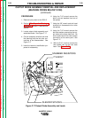
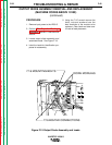
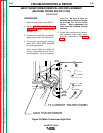
6. Using 7/16” wrench remove the top
and bottom mounting bolts and
associated washers from the diode
module to be replaced.
7. Using 1/8” Allen wrench remove the
center socket head cap screw from
the diode module to be replaced.
8. Carefully remove the diode module.
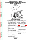
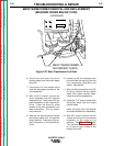
9. To install the new module first make
sure the heat sink surface is clean
and free of dirt.
10. Apply a thin even coating (.004 to
.010 IN.) of thermal compound
Penetrox A13 (Lincoln E2529) to
the bottom surface of the base
plate. Keep the compound away
from the mounting hole areas.
11. Apply a small amount of Loctite
#271 (Lincoln E1777-1) to the first
three threads of the socket head
cap screw.
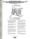
12. Start threading the top and bottom
screws and associated washers by
hand. Also start the center socket
head cap screw and associated
washer.
13. Run the center cap screw in by
hand until it makes contact with the
surface of the module. Do not
torque down yet!
14. Tighten the top and bottom screws
to between 5.0 and 10.0 IN-LBS.
15. Tighten the center cap screw to
between 12 and 18 IN-LBS.
16. Further tighten the top and bottom
screws to between 30 and 40
IN-LBS.
17. Connect the leads to the proper ter-
minals and tighten the screws to
between 30 to 40 IN-LBS. Do not
stress the module terminals when
making these connections.
18. Clear all leads and prepare unit for
reassembly of wrap-around case.
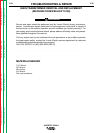
OUTPUT DIODE ASSEMBLY REMOVAL AND REPLACEMENT
(MACHINE CODES ABOVE 10150)
(continued)