


E-3
THEORY OF OPERATION
E-3
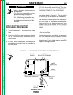
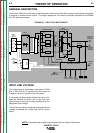
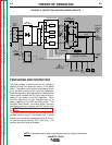
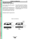
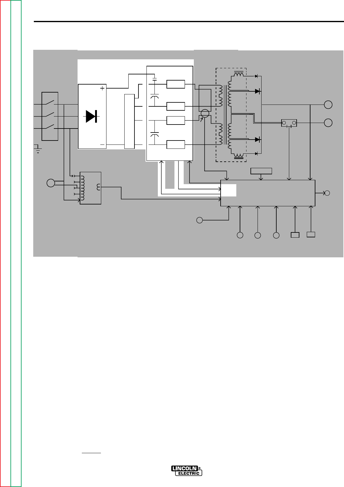
PRECHARGE AND PROTECTION
The input voltage is rectified and the DC voltage is
applied, through the reconnect switch, to the power
board. The power board contains precharging circuit-
ry for the safe charging of the input filter capacitors.
Once the capacitors are precharged and balanced the
control board activates the CR1 input relay which con-
nects full input power to the filter capacitors. When
the filter capacitors are fully charged they act as
power supplies for the IGBT switching circuit. The
Insulated Gate Bipolar Transistors supply the main
transformer primary windings with DC current flow.
See
IGBT Operation Discussion and diagrams
in
this section.
The power board also monitors the filter capacitors for
voltage balance and/or overvoltage and, if either
should occur, sends the appropriate signal to the con-
trol board to deactivate the CR1 input relay. The
machine output will also be disabled.
FIGURE E.2 PROTECTION AND PRE-CHARGE CIRCUITS
INVERTEC V250-S
INPUT
LINE
SWITCH
INPUT
RECTIFIER
R
E
C
O
N
N
E
C
T
S
W
I
T
C
H
AUXILIARY
TRANSFORMER
FAN
MOTORS
POWER BOARD
MAIN
TRANSFORMER
SHUNT
POSITIVE
OUTPUT
TERMINAL
NEGATIVE
OUTPUT
TERMINAL
THERMAL
LIGHT
REMOTE
RECEPTACLE
OUTPUT
CONTROL
STRIKE
CONTROL
ARC
FORCE
CONTROL
MODE
SWITCH
LOCAL/
REMOTE
SWITCH
RELAY
CAPACITOR
CAPACITOR
IGBT
IGBT
IGBT
IGBT
CURRENT
TRANSFORMER
18VAC
GATE SIGNALS
THERMOSTATS
O
V
E
R
V
O
L
T
A
G
E
PROTECTION SIGNAL
CR1 RELAY DRIVE SIGNAL
CR1
IGBT
CONTROL BOARD
A"
L
E
A
D
"
F
E
E
D
B
A
C
K
F
E
E
D
B
A
C
K
NOTE: Unshaded areas of block logic diagrams are the subject of discussion.
Return to Section TOC Return to Section TOC Return to Section TOC Return to Section TOC
Return to Master TOC Return to Master TOC Return to Master TOC Return to Master TOC