


Return to Section TOC Return to Section TOC Return to Section TOC Return to Section TOC
Return to Master TOC Return to Master TOC Return to Master TOC Return to Master TOC
F-59
TROUBLESHOOTING & REPAIR
F-59
INVERTEC V250-S
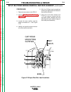
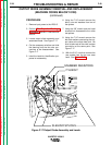
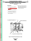
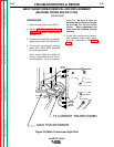
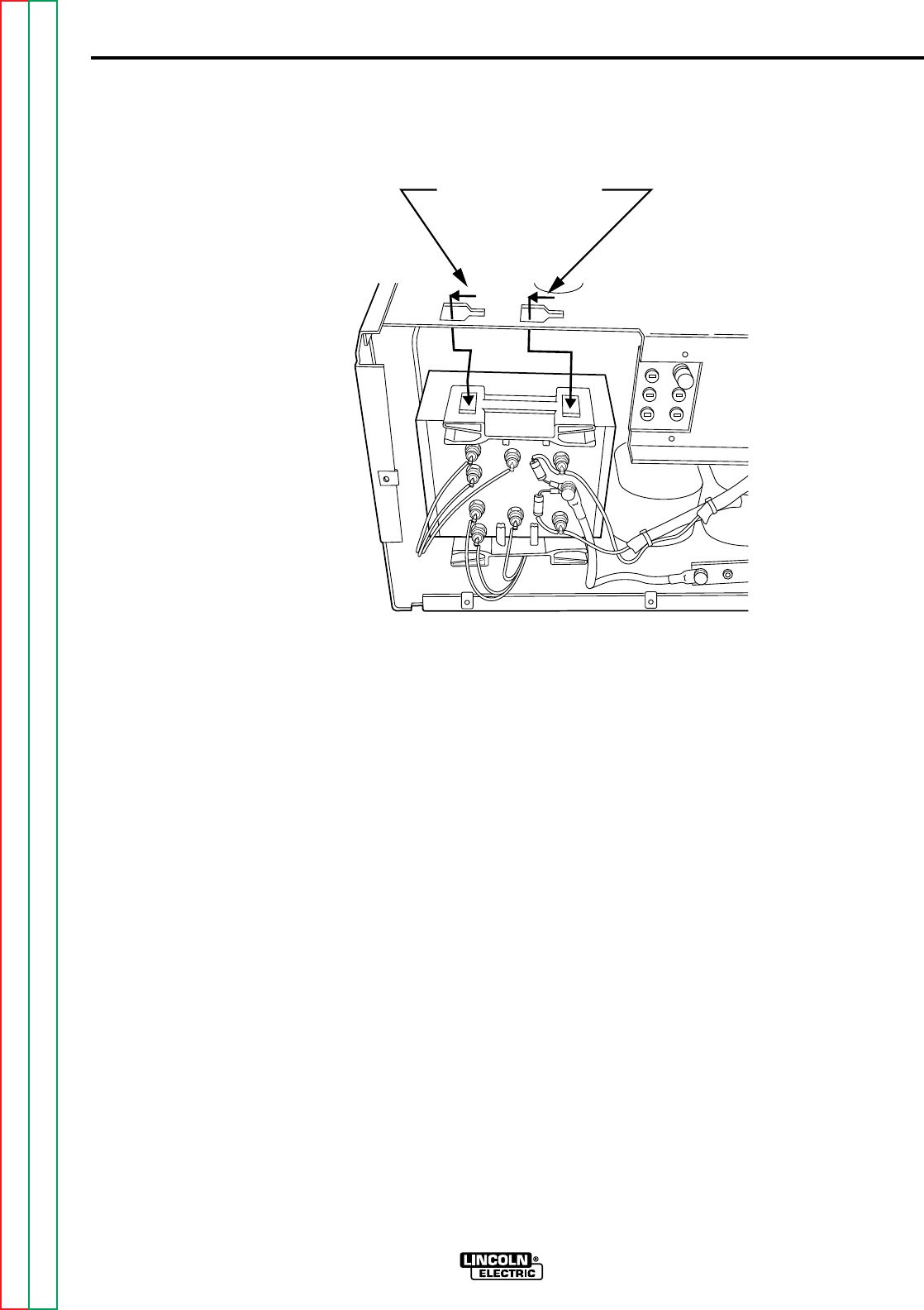
10. Using the slot head screwdriver
carefully disengage the output
diode heat sink mounting bracket
from the top center panel. Also dis-
engage the bottom heat sink
mounting bracket from the support
bracket. This can be accomplished
by lifting the locking tab and sliding
the heat sink assembly towards the
rear of the machine. See Figure
F.18.
11. Carefully remove the output diode
assembly from the V250-S.
12. Remove the two heat sink holders
from the heat sink/diode assembly.
13. Assemble the two heat sink holders
to the new heat sink/diode assem-
bly.
14. Install the new output diode assem-
bly into position and slide it towards
the front of the machine until the
locking tabs (both top and bottom)
are engaged. See Figure F.18.
15. Install the two screws into the top
rear case back. See
Figure F.15
.
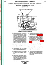
16 Using the 7/16” wrench, bolt and
washers connect the output cable to
the diode heat sink. Be sure to take
note of the small resistor connection
at the same point. See
Figure
F.17
.
17. Using the 7/16” wrench, bolts, nuts
and washers assemble and tighten
the two splices.
18. Using the 3/8” wrench and slot
head screwdriver assemble and
tighten the other two splices.
19. Position sleeving and secure with
cable ties. Clear all leads and pre-
pare unit for reassembly of wrap-
around case.
OUTPUT DIODE ASSEMBLY REMOVAL AND REPLACEMENT
(MACHINE CODES BELOW 10150)
(continued)
LOCKING TABS
Figure F.18 Heatsink Removal