


Return to Section TOC Return to Section TOC Return to Section TOC Return to Section TOC
Return to Master TOC Return to Master TOC Return to Master TOC Return to Master TOC
F-73
TROUBLESHOOTING & REPAIR
F-73
INVERTEC V250-S
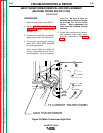
7. Disconnect the thermostat leads
from the thermostat mounted on the
shunt assembly.
8. With the 3/4” wrench remove the
shunt assembly from the negative
output terminal. Take note of the by-
pass connection on the negative ter-
minal. Clear the shunt to allow
access to the main transformer and
lead connections. Cut any neces-
sary cable ties.
9. With the 3/4” wrench remove the
positive output lead from the positive
output terminal. Take note of the by-
pass connection on the positive ter-
minal.
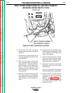
10. Locate and cut the necessary wire
ties and slide the sleeving from the
two transformer reactor lead
splices.
11. With slot head screwdriver and 3/8”
nut-driver remove the two reactor
leads from output the rectifier
leads. Label the leads for
reassembly.
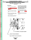
12. Using the 7/16” wrench remove the
four secondary leads from the out-
put rectifier module. Label the leads
and note washer and lead place-
ment for reassembly. See Figure
F.24.
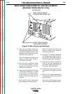
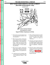
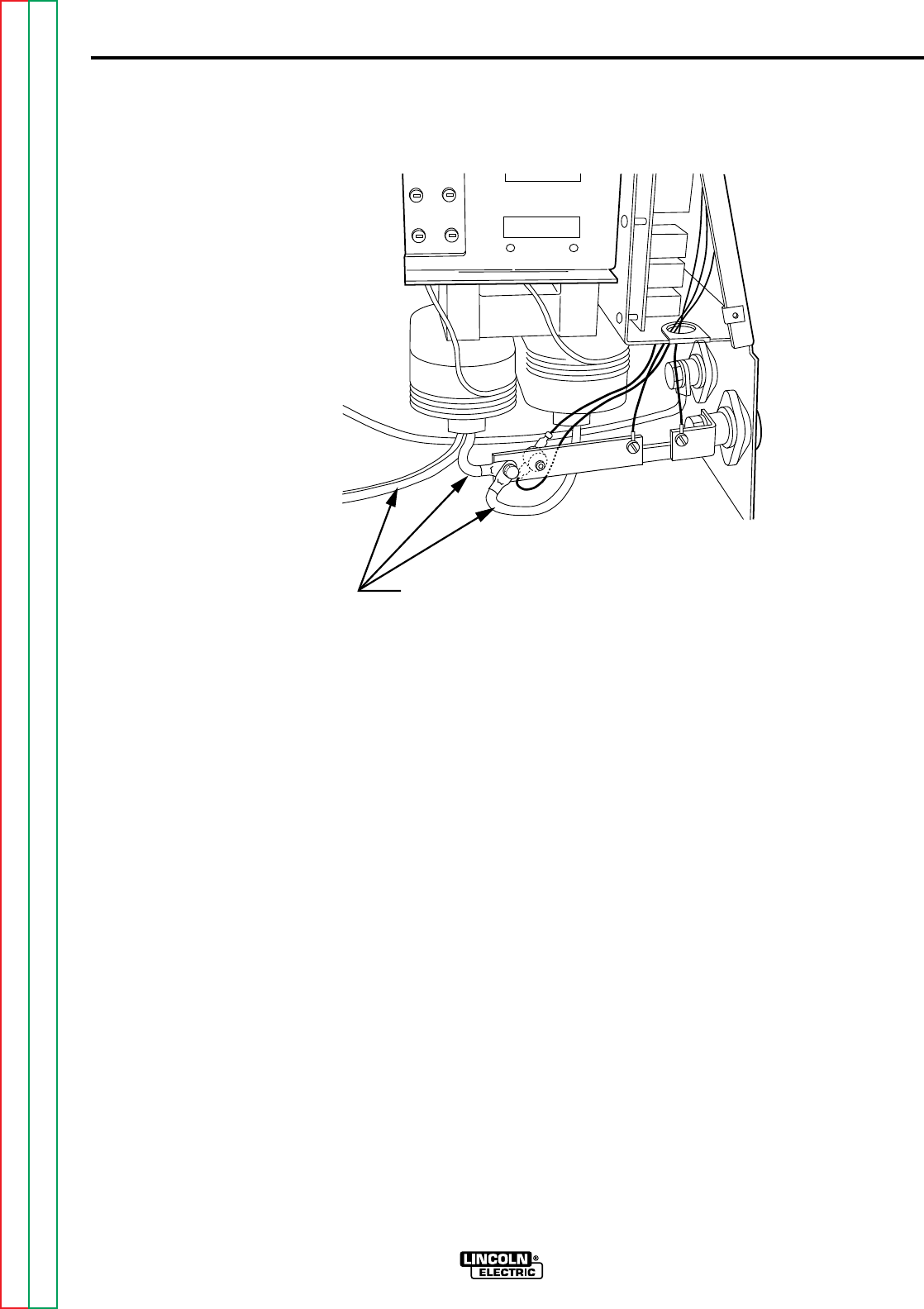
13. With 3/8” wrench remove the two
screws mounting the transformer
assembly to the base of the
machine. See
Figure F.25
. Note:
The machine will have to be tilted
on its side to gain access to the
bottom of the unit.
MAIN TRANSFORMER REMOVAL AND REPLACEMENT
(MACHINE CODES ABOVE 10150)
(continued)
MAIN TRANSFORMER
SECONDARY LEADS
Figure F.24 Main Transformer Left Side