


A-5
INSTALLATION
INVERTEC V250-S
A-5
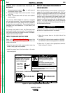
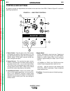
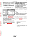
OUTPUT CONNECTIONS
Refer to figure A.2 for the location of the 6 Pin Remote
Receptacle and the Output Terminals.
FIGURE A.2 OUTPUT CONNECTIONS
REMOTE CONTROL RECEPTACLE
Remote control (K857), Arc start switch (K814), Hand
amptrol (K963) and Foot amptrol (K870) connect
directly to 6 pin amphenol on the front of the unit.
OUTPUT CABLES
Select the output cable size based on Table A.1.
TABLE A.1
Cable Sizes for Combined Length of Electrode and
Work Cable ( Copper Cable Rated at 75°C).
Length Cable Size
up to 150 ft.(46m) 1/0 (50mm
2
)
up to 250 ft.(72m) 2/0 (70mm
2
)
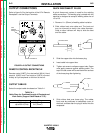
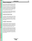
QUICK DISCONNECT PLUGS
A quick disconnect system is used for the welding
cable connections. The welding plug included with the
machine is designed to accept a welding cable size of
1/0 to 2/0.
1. Remove 1 in. (25mm) of welding cable insulation.
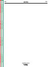
2. Slide rubber boot onto cable end. The boot end
may be trimmed to match the cable diameter.
Soap or other lubricant will help to slide the boot
over the cable.
3. Slide the copper tube into the brass plug.
4. Insert cable into copper tube.
5. Tighten set screw to collapse copper tube. Screw
must apply pressure against welding cable. The
top of the set screw will be well below the surface
of the brass plug after tightening.
6. Slide rubber boot over brass plug. The rubber
boot must be positioned to completely cover all
electrical surfaces after the plug is locked into the
receptacle.
Return to Section TOC Return to Section TOC Return to Section TOC Return to Section TOC
Return to Master TOC Return to Master TOC Return to Master TOC Return to Master TOC
25 mm
1 in.
WELDING CABLE
BOOT
TRIM
SET SCREW
BRASS PLUG
COPPER TUBE
O
I
INVERTEC V250-S
¤
S
-
+
1
15
50
85
120
170
230
250
A
OUTPUT
SMAW
SOFT
GTAW
SMAW
CRISP
REMOTE
LOCAL
THERMAL
HOT START
1
2
3
4
6
7
8
9
10
5
0
ARC FORCE
1
2
3
4
6
7
8
9
10
5
0
OUTPUT TERMINALS
6 PIN
REMOTE
RECEPTACLE