


A-3
INSTALLATION
INVERTEC V250-S
A-3
Read this entire installation section before you
start installation.
SAFETY PRECAUTIONS
ELECTRIC SHOCK can kill.
• Have an electrician install and ser-
vice this equipment.
• Turn the input power off at the fuse
box before working on equipment.
• Do not touch electrically hot parts.
• Be sure to discharge capacitors with
the procedure outlined in the
Maintenance Section of this manual
before working in that area of the
equipment.
---------------------------------------------------------------------
SELECT SUITABLE LOCATION
The Invertec V250-S will operate in harsh environ-
ments. Even so, it is important that simple preventa-
tive measures are followed in order to assure long life
and reliable operation.
• The machine must be located where there is free cir-
culation of clean air such that air movement in the
back and out the front will not be restricted.
• Dirt and dust that can be drawn into the machine
should be kept to a minimum. Failure to observe
these precautions can result in excessive operating
temperatures and nuisance shutdown.
• Keep machine dry. Shelter from rain and snow. Do
not place on wet ground or in puddles.
STACKING
V250-S’s cannot be stacked.
TILTING
Place the machine directly on a secure, level surface
or on a recommended undercarriage. The machine
may topple over if this procedure is not followed.
HIGH FREQUENCY PRECAUTIONS
If possible locate the V250-S away from radio con-
trolled machinery. The normal operation of the
V250-S may adversely affect the operation of RF con-
trolled equipment, which may result in bodily injury or
damage to the equipment.
INPUT CONNECTIONS
The Invertec V250-S should be connected only by a
qualified electrician. Installation should be made in
accordance with all local and national electric codes
and the information detailed below.
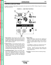
GROUND CONNECTION
Ground per National Electrical Code for 60Hz
machines connect the green lead to earth ground.
For 50/60Hz machines connect the ground terminal
marked located in the machine on the lower right
side the base of the welder to earth ground.
INPUT SUPPLY CONNECTIONS
Be sure the voltage phase and frequency of the input
power is as specified on the rating plate, located on
the rear of the machine.
Supply line entry provision is in the case rear panel.
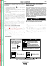
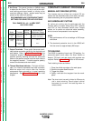
POWER INPUT CONNECTION FOR 60HZ
MACHINES
A 10 ft. power cord is provided and wired into the
machine. Follow the power cord connection instruc-
tions. Incorrect connection may result in equipment
damage.
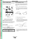
Single Phase Input:
Connect green lead to ground
per U.S. National Electrical Code. Connect black and
white leads to power. Wrap red lead with tape to pro-
vide 600V insulation.
Three Phase Input:
Connect green lead to ground
per U.S. National Electrical Code. Connect black, red
and white leads to power.
Return to Section TOC Return to Section TOC Return to Section TOC Return to Section TOC
Return to Master TOC Return to Master TOC Return to Master TOC Return to Master TOC
WARNING