


Return to Section TOC Return to Section TOC Return to Section TOC Return to Section TOC
Return to Master TOC Return to Master TOC Return to Master TOC Return to Master TOC
F-32
TROUBLESHOOTING & REPAIR
F-32
INVERTEC V250-S
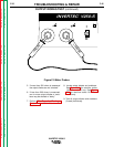
TEST PROCEDURE
1. Remove main input power to the
V250-S.
2. Perform
Filter Capacitor
Discharge Procedure
detailed in
Maintenance Section.
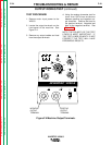
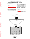
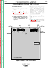
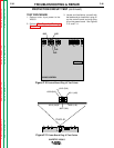
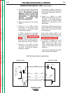
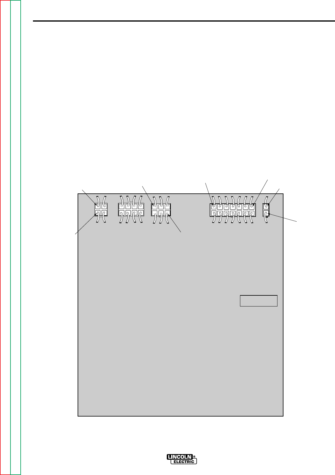
3. Locate and familiarize yourself with
the leads and pin locations in plugs
J1 thru J5 on the control board. See
Figure F.9.
4. The following tests will be performed
with the input power applied to the
V250-S. BE CAREFUL. ALWAYS
REMOVE INPUT POWER AND
PERFORM FILTER CAPACITOR
DISCHARGE PROCEDURE
BEFORE TOUCHING ANY
MACHINE COMPONENT.
5. Apply input power and turn ON the
V250 -S.
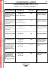
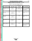
6. Perform the voltage checks outlined
in
Table F.5
. making sure all of the
test conditions are in effect.
CONTROL BOARD VOLTAGE TEST (continued)
G2666-[ ]
V250S CONTROL
J1
J2 J5 J3 J4
1J1
(RED LEAD)
3J1
(RED LEAD)
4J5
(#318)
1J5
(#322)
2J4
(WHITE LEAD)
1J4
(BLACK LEAD)
7J3
(#303)
1J3
(#375)
Figure F.9 Plugs J1-J5 on Control Board