


Return to Section TOC Return to Section TOC Return to Section TOC Return to Section TOC
Return to Master TOC Return to Master TOC Return to Master TOC Return to Master TOC
F-29
TROUBLESHOOTING & REPAIR
F-29
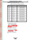
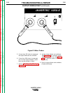
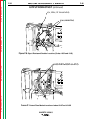
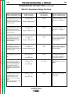
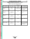
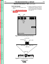
POWER BOARD VOLTAGE TEST (continued)
INVERTEC V250-S
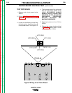
TABLE F.4. Power Board Voltage Test Points.
TEST DESCRIPTION
The PWM pulse drive from the
control board to the pulse
transformer primary located on
the power board.
The PWM pulse drive from the
control board to the pulse
transformer primary located on
the power board.
The PWM pulse drive from the
control board to the pulse
transformer primary located on
the power board.
The PWM pulse drive from the
control board to the pulse
transformer primary located on
the power board.
CR1 (charge relay) coil volt-
age.
This low voltage will be pre-
sent when the protection cir-
cuit has determined that the
filter capacitor voltage is
acceptable. Note: The CR1
charge relay should be acti-
vated.
This voltage will be present
unit the protection circuit
determines that the filter
capacitor is at an acceptable
level.
Note: The CR1 charge relay
will not be activated.
TEST POINTS
Lead #307 (2J6)
to
Negative output terminal
Lead #308 (1J6)
to
Negative output terminal
Lead #307 (2J6)
to
Negative output terminal
Lead #308 (1J6)
to
Negative output terminal
Lead #309 (6J6)+
to
lead #310 (3J6)
Lead #311 (4J6)+
to
lead #313 (5J6)-
Lead #311 (4J6)+
to
lead #313 (5J6)-
ACCEPTABLE
VOLTAGES
14VDC.
14VDC.
7VDC.
7VDC.
12VDC
0 to 1VDC.
15VDC.
TEST CONDITIONS
No load on the machine - the
mode switch in SMAW posi-
tion.
No load on the machine - the
mode switch in SMAW posi-
tion.
Machine loaded to 250Amps.
The output control R3 at the
maximum position.
Machine loaded to 250Amps.
The output control R3 at the
maximum position.
This voltage should be pre-
sent only after the protection
circuit as been satisfied.
If voltage protection circuit IS
satisfied.
If voltage protection circuit is
NOT satisfied.