


F-24
TROUBLESHOOTING & REPAIR
F-24
TEST PROCEDURE
1. Remove main input power to the
V250-S.
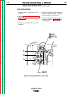
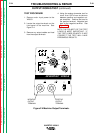
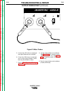
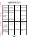
2. Locate the output terminals on the
front panel of the machine. See
Figure F.4.
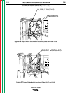
3. Remove any output cables and load
from the output terminals.
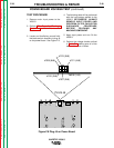
4. Using the analog ohmmeter test for
more than 200 ohms resistance
between positive and negative out-
put terminals. Positive test lead to
the positive terminal; Negative test
lead to the negative terminal. See
Figure F.5.
NOTE: THE POLARITY OF THE TEST
LEADS IS MOST IMPORTANT. IF
THE TEST LEADS POLARITY IS NOT
CORRECT THE TEST WILL HAVE
ERRONEOUS RESULTS.
OUTPUT DIODES TEST (continued)
INVERTEC V250-S
Return to Section TOC Return to Section TOC Return to Section TOC Return to Section TOC
Return to Master TOC Return to Master TOC Return to Master TOC Return to Master TOC
O
I
INVERTEC V250-S
®
S
-
+
1
15
50
85
120
170
230
250
A
OUTPUT
SMAW
SOFT
GTAW
SMAW
CRISP
REMOTE
LOCAL
THERMAL
HOT START
1
2
3
4
6
7
8
9
10
5
0
ARC FORCE
1
2
3
4
6
7
8
9
10
5
0
POSITIVE
OUTPUT
TERMINAL
NEGATIVE
OUTPUT
TERMINAL
Figure F.4 Machine Output Terminals.