


F-17
TROUBLESHOOTING & REPAIR
F-17
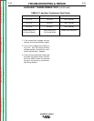
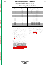
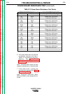
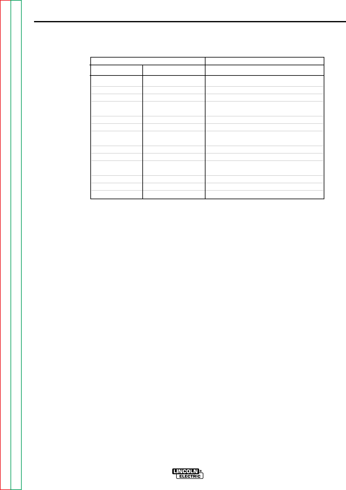
6. If the Input Rectifier does not meet
the acceptable readings outlined in
Table F.2. the component may be
faulty. Replace.
Note: Before replacing the Input
Rectifier(D9) check the input
power switch (S1) and perform
the
Power Board Resistance
Test
. Also check for leaky or
faulty filter capacitors.
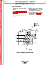
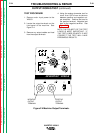
7. When installing a new Input
Rectifier, torque the mounting nuts to
44IN-LBS. A thin coating of Dow
Corning 340 Heat Sink Compound
(Lincoln E1868) is recommended.
Torque the lead terminals to 31IN-
LBS. See
Input Rectifier Bridge
Removal And Replacement
.
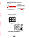
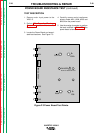
8. If the Input Rectifier is good be sure
to reconnect leads #207, #207A and
#209 to the correct terminals and
torque to 31IN-LBS. See wiring dia-
gram and Figure F.2.
INPUT RECTIFIER TEST (continued)
INVERTEC V250-S
Return to Section TOC Return to Section TOC Return to Section TOC Return to Section TOC
Return to Master TOC Return to Master TOC Return to Master TOC Return to Master TOC
TEST POINT TERMINALS ANALOG METER X10 RANGE
+ Probe - Probe Acceptable Meter Readings
A 207 Greater than 1000 ohms
B 207 Greater than 1000 ohms
C 207 Greater than 1000 ohms
A 209 Less than 100 ohms
B 209 Less than 100 ohms
C 209 Less than 100 ohms
207 A Less than 100 ohms
207 B Less than 100 ohms
207 C Less than 100 ohms
209 A Greater than 1000 ohms
209 B Greater than 1000 ohms
209 C Greater than 1000 ohms
TABLE F.2 Input Rectifier Test Points