


F-58
TROUBLESHOOTING & REPAIR
F-58
PROCEDURE
1. Remove input power to the V250-S.
2. Perform
Filter Capacitor Discharge
Procedure
detailed in Maintenance
Section.
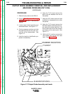
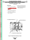
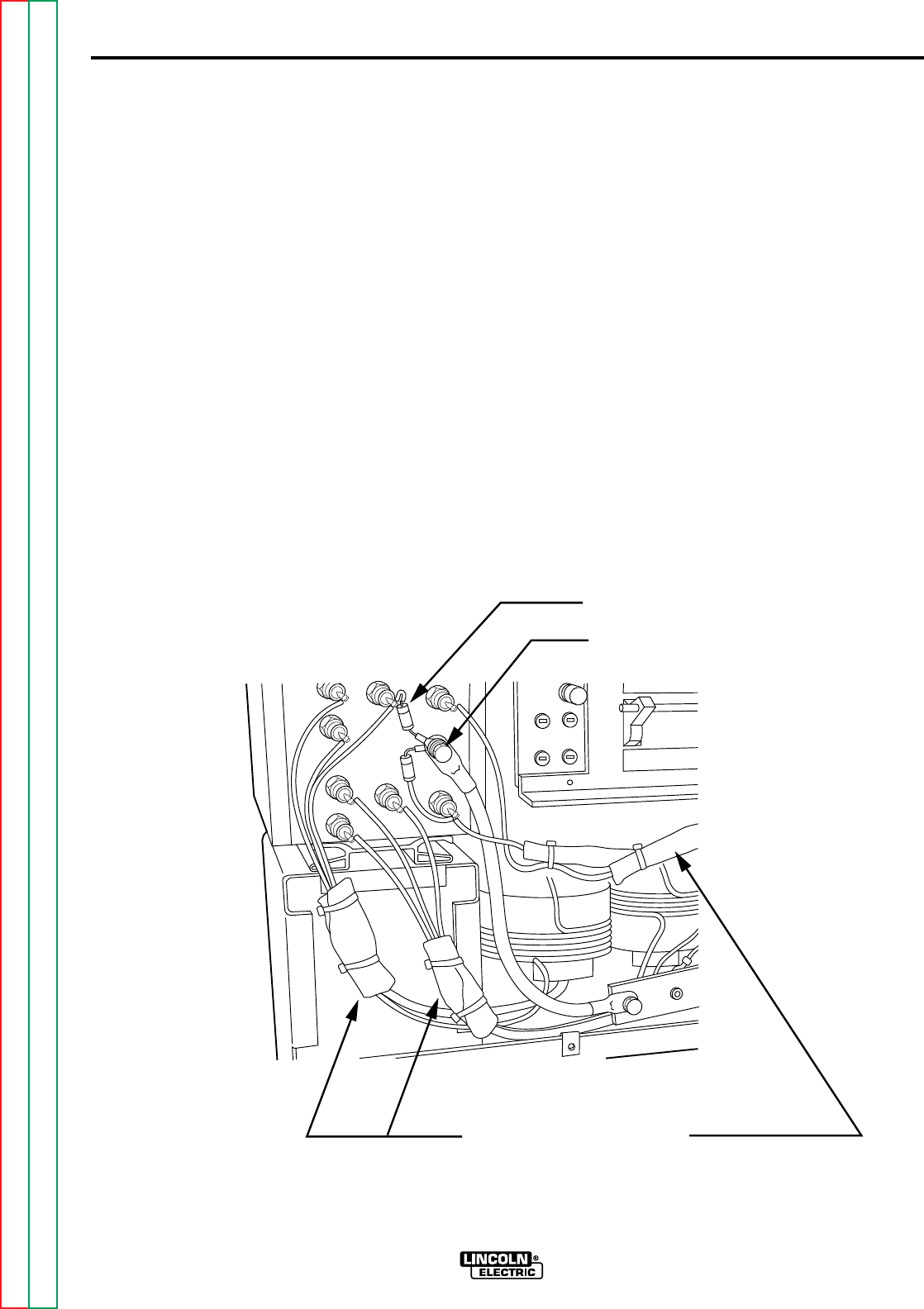
3. Locate output diode assembly and
associated leads. See Figure F.17.
4. Cut the necessary wire ties and slide
the sleeving from the four wire con-
nections to be disassembled. See
Figure F.17
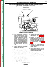
5. Label the leads for identification pur-
poses for reassembly.
6. Using the 7/16” wrench remove the
bolts, nuts and washers from two of
the splices.
7. Using the 3/8” wrench and slot head
screwdriver disassemble the other
two splices.
8. Using the 7/16” wrench remove the
bolt and washers connecting the out-
put cable to the diode heat sink. Be
sure to take note of the small resistor
connection at the same point. See
Figure F.17.
9. With the 5/16” nut-driver remove the
two screws from the top rear case
back. See
Figure F.15
.
OUTPUT DIODE ASSEMBLY REMOVAL AND REPLACEMENT
(MACHINE CODES BELOW 10150)
(continued)
INVERTEC V250-S
Return to Section TOC Return to Section TOC Return to Section TOC Return to Section TOC
Return to Master TOC Return to Master TOC Return to Master TOC Return to Master TOC
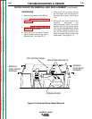
SLEEVED SPLICES
SNUBBER RESISTORS
7/16 BOLT
Figure F.17 Output Diode Assembly and Leads