


F-40
TROUBLESHOOTING & REPAIR
F-40
TEST PROCEDURE
1. Remove main input power to the
V250-S.
2. Perform
Filter Capacitor Discharge
Procedure
detailed in Maintenance
Section.
3. Put the mode switch S2 in the
SMAW (soft) position and put the
Local/Remote switch S3 in the
LOCAL position.
4. Put the Output Control R3 at the
minimum position.
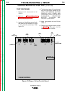
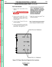
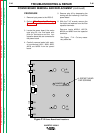
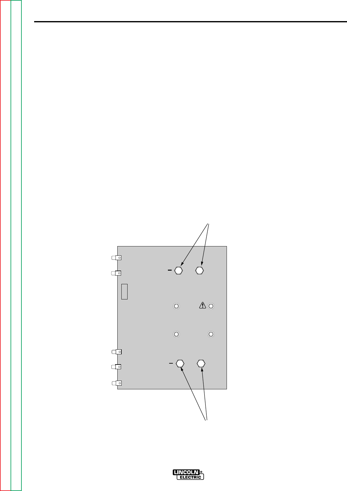
5. Locate and familiarize yourself with
the capacitor test locations on the
power board. See Figure F.12.
6. The following tests will be performed
with the input power applied to the
V250-S.
BE CAREFUL. ALWAYS
REMOVE THE INPUT POWER AND
PERFORM FILTER CAPACITOR
DISCHARGE PROCEDURE
BEFORE TOUCHING ANY
MACHINE COMPONENT.
7. Apply the correct input power
†
and
turn ON the V250-S.
† Note: This test should only be conducted
with the V250-S reconnect switch and “A”
jumper configured for 380VAC and above.
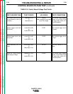
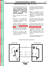
CAPACITOR BALANCE TEST (continued)
INVERTEC V250-S
Return to Section TOC Return to Section TOC Return to Section TOC Return to Section TOC
Return to Master TOC Return to Master TOC Return to Master TOC Return to Master TOC
V250S POWER G2684
DANGER
HIGH VOLTAGE CAN KILL
204
201
209
208
205
207A
202A
203A
206
+
+
CAPACITOR (C2) TERMINALS
CAPACITOR (C1) TERMINALS
Figure F.12 Power Board and Capacitor Test Locations