


E-4
THEORY OF OPERATION
E-4
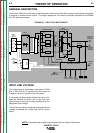
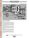
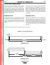
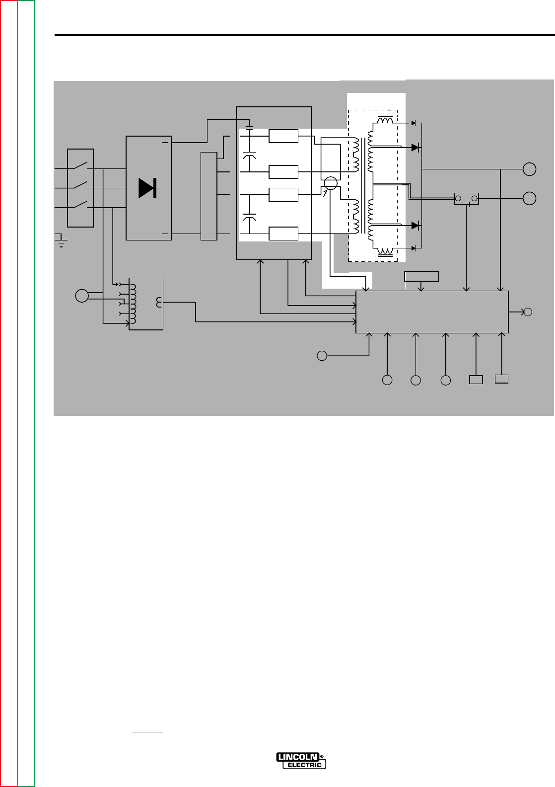
MAIN TRANSFORMER
Each IGBT pair acts as a switch assembly. Each
assembly feeds a separate, oppositely wound primary
winding of the main transformer. The reverse direc-
tions of current flow through the main transformer pri-
maries and the offset timing of the IGBT pairs induce
an AC square wave output signal at the secondary of
the main transformer.
The DC current flow through each primary winding is
redirected or “clamped” back to each respective filter
capacitor when the IGBTs are turned off. This is
needed due to the inductance of the transformer pri-
mary winding.
The primary currents also pass through the current
transformer which sends a signal to the control board.
If the primary currents are not equal the control board
compensates by adjusting the IGBT gate signals.
The firing of both IGBT pairs occurs during halves of
the 50 microsecond intervals, creating a constant 20
KHZ output.
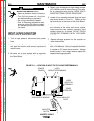
FIGURE E.3 MAIN TRANSFORMER
INVERTEC V250-S
INPUT
LINE
SWITCH
INPUT
RECTIFIER
R
E
C
O
N
N
E
C
T
S
W
I
T
C
H
AUXILIARY
TRANSFORMER
FAN
MOTORS
POWER BOARD
MAIN
TRANSFORMER
SHUNT
POSITIVE
OUTPUT
TERMINAL
NEGATIVE
OUTPUT
TERMINAL
THERMAL
LIGHT
REMOTE
RECEPTACLE
OUTPUT
CONTROL
STRIKE
CONTROL
ARC
FORCE
CONTROL
MODE
SWITCH
LOCAL/
REMOTE
SWITCH
RELAY
CAPACITOR
CAPACITOR
IGBT
IGBT
IGBT
IGBT
CURRENT
TRANSFORMER
18VAC
GATE SIGNALS
THERMOSTATS
O
V
E
R
V
O
L
T
A
G
E
PROTECTION SIGNAL
CR1 RELAY DRIVE SIGNAL
CR1
IGBT
CONTROL BOARD
A"
L
E
A
D
"
F
E
E
D
B
A
C
K
F
E
E
D
B
A
C
K
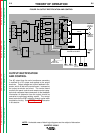
NOTE: Unshaded areas of block logic diagrams are the subject of discussion.
Return to Section TOC Return to Section TOC Return to Section TOC Return to Section TOC
Return to Master TOC Return to Master TOC Return to Master TOC Return to Master TOC