


Return to Section TOC Return to Section TOC Return to Section TOC Return to Section TOC
Return to Master TOC Return to Master TOC Return to Master TOC Return to Master TOC
F-66
TROUBLESHOOTING & REPAIR
F-66
INVERTEC V250-S
PROCEDURE
1. Remove input power to the V250-S.
2. Perform
Filter Capacitor Discharge
Procedure
detailed in Maintenance
Section.
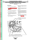
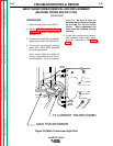
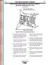
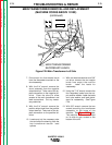
3. Locate main transformer and associ-
ated primary leads. See Figure F.20.
4. Disconnect transformer primary
leads #201, #204, #205 and #208
from the power board.
Note: Leads #204 and #205 will
have to be removed from the T3 cur-
rent transformer. Cut any necessary
cable ties. Be sure to note the
direction that the leads are thread-
ed through the current trans-
former. Upon reassembly the
leads must be threaded through
correctly.
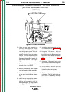
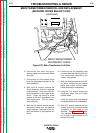
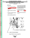
5. Locate main transformer and associ-
ated secondary leads, reactor leads,
and shunt connections. See Figure
F.21.
MAIN TRANSFORMER REMOVAL AND REPLACEMENT
(MACHINE CODES BELOW 10150)
(continued)
201
204
205
208
T3 CURRENT TRANSFORMER
MAIN TRANSFORMER
Figure F.20 Main Transformer Right Side