


F-36
TROUBLESHOOTING & REPAIR
F-36
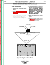
TEST PROCEDURE
1. Remove main input power to the
V250-S.
2. Perform
Filter Capacitor Discharge
Procedure
detailed in Maintenance
Section.
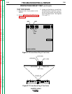
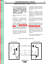
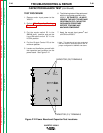
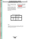
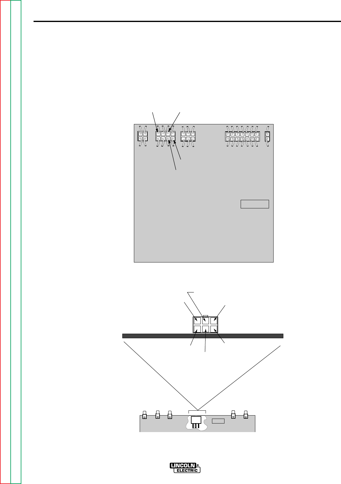
3. Locate and familiarize yourself with
the leads and pin locations in plug J2
on the control board and also plug
J6 on the power board. See Figures
F.10. and F.11.
PROTECTION CIRCUIT TEST (continued)
INVERTEC V250-S
Return to Section TOC Return to Section TOC Return to Section TOC Return to Section TOC
Return to Master TOC Return to Master TOC Return to Master TOC Return to Master TOC
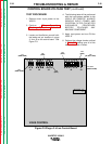
G2666-[ ]
V250S CONTROL
J1
J2 J5 J3 J4
1J2
8J2
6J2
2J2
Figure F.10 Control Board Plug J2 Test Points
V250S POWER G2684
204
201
209
208
205
J6
PLUG J6
#308 (1J6)
#307 (2J6)
#309 (6J6)
#310 (3J6)
#311 (4J6)
#313 (5J6)
Figure F.11 Power Board Plug J6 Test Points