


Return to Section TOC Return to Section TOC Return to Section TOC Return to Section TOC
Return to Master TOC Return to Master TOC Return to Master TOC Return to Master TOC
F-33
TROUBLESHOOTING & REPAIR
F-33
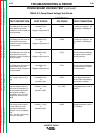
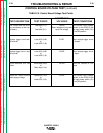
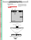
CONTROL BOARD VOLTAGE TEST (continued)
INVERTEC V250-S
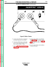
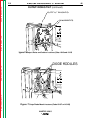
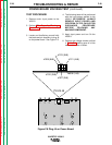
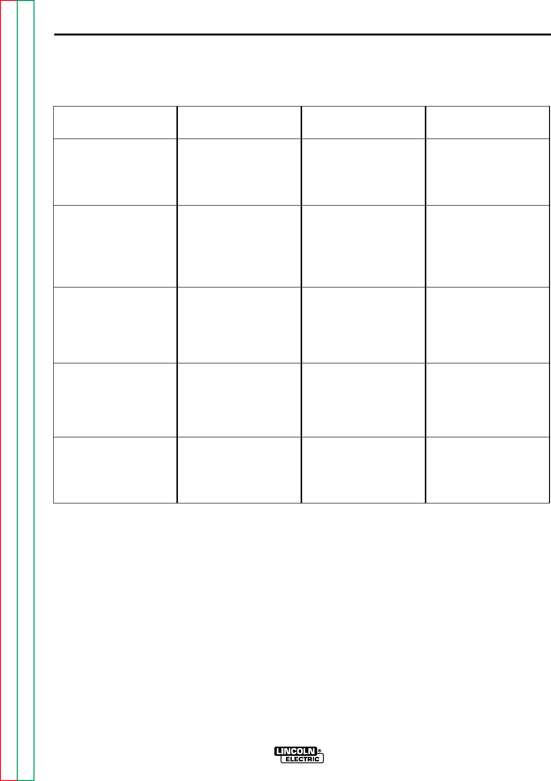
TABLE F.5. Control Board Voltage Test Points.
TEST DESCRIPTION
The 18VAC from the auxil-
iary transformer to the con-
trol board.
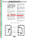
Remote trigger circuit test.
(#2 and #4)
Remote trigger circuit test.
(#2 and #4)
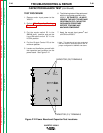
Shunt feedback milli-volt
check.
Check for 15VDC control
board supply voltage.
TEST POINTS
Red lead (1J1)
to
Red lead (3J1)
Lead #318 (4J5)
to
Lead #322 (1J5)
Lead #318 (4J5)
to
Lead #322 (1J5)
White lead (2J4)+
to
Black lead (1J4)-
Lead #303 (7J3)+
to
Lead #375 (1J3)-
ACCEPTABLE
VOLTAGES
18VAC
Note: voltage will vary with
input line voltage.
0 VDC.
12VDC.
100 mV.
15VDC.
TEST CONDITIONS
The correct input voltage
applied to the V250-S and
the input power switch (S1)
in the ON position.
When remote trigger circuit
is “closed”.
When remote trigger circuit
is “open”.
Machine loaded to 120
Amps
The correct input voltage
applied to the V250-S and
the input power switch (S1)
in the ON position.