


96 Operating the Meter
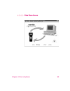
The fiber optic link system also allows the meter and probe to be
separated by up to 50 meters. One application is surveying
towers. A skilled climber carries the probe while the person
actually making the measurements remains on the ground.
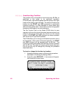
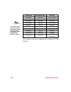
Controls and Indicators
The fiber optic transmitter has the following controls and
indicators:
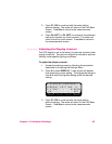
Control Function Indication
BAT Test
S1 OFF
ON
Tests Battery Charge
Turns Battery Off
Turns Power On
LED On
a
LED Off
LED Off
CAL 1
S2 NORM
CAL 2
Tests Channel 1
Normal Operation
Tests Channel 2
Meter mid-scale
Variable Level
Above mid-scale
a. The battery is considered charged when above 15.0 Vdc.
Setting the Meter
The meter has two input ports to receive information from
probes:
•
The standard probe cable input
•
The fiber optic receiver input
Only one input can be in use at any time. The default input upon
turn-on is the last input port used. It is important to remember
this if you switch back and forth between using the standard
input and the fiber optic receiver.