


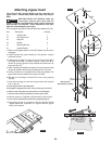
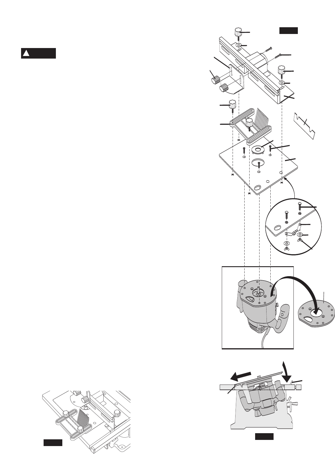
Attaching Router Insert
The following Skil Router Models may be used with the router
insert: Models 1810, 1815, and 1820.
BEFORE USING THE ROUTER: Read the
instruction manual that came with the router.
For additional operating information including when to use the Shim R9,
s
ee page 94.
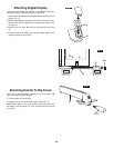
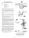
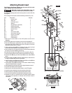
From among the loose parts, locate the following hardware (Fig. 22).
I
tem Description Quantity
R1 Router Insert 1
R2 Wing Nut 2
R
3 Hex-head screw 2
R4 Washer 4
R5 Ring Reducer (assorted) 5
R6 Retaining Bracket 1
R7 Phillips Head Screw 3
R8 Router Fence 1
R9 Shim 1
R10 Screw Knob Male 4
R11 Screw Knob Female 4
R12 Router Guard Bolt 4
R13 Safety Guard 1
R14 Featherboard 1
1. Make sure the router switch is in the OFF position and the cord is
unplugged.
2. Place router upside down on table top and remove the baseplate
T.
3. Place insert
R1 atop the upside-down router, align the flat side on the
router base with the flat indent on the insert and fasten it with three
screws R7 as shown above. (Fig. 22)
4. Attach retaining bracket
R6 onto bottom of insert using hex-head
screws R3, washers R4 and wing nuts R2 as shown.
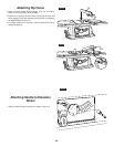
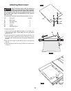
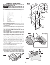
5. Lift the red latch lever
Y located at front of the left wing opening. Note that
the router can only be installed on the left wing.
6. Slip tabs
X on the edge of insert R1 into rear of wing opening. (Fig. 23)
7.
Lower front edge of insert into wing and lower the red latch lever Y. (Fig. 23)
8. Install the fence R8 using two male knobs R10 and two washers R4 as
shown.
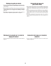
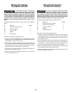
9. Install the reducing ring
R5 to match the cutter diameter, unless the bit is
too large to operate safely with the ring installed.
10. Install the safety guard
R13 using female knobs R11 and bolts R12 as
shown. Adjust to the height of the workpiece.
11. Install feather board
R14 according to the section entitled “Routing
Using The Feather Board” on page 92.
12.
Install appropriate router bit per the router’s original instruction manual.
13. Lock the router switch to the ON position.
14. Make sure the main table saw power switch is in the OFF position.
15. Insert the router electrical plug into the accessory power outlet.
16. See the section on “Operation of the Accessory Power Outlet”.
17. Lower the saw blade below the table before operating the router.
18. Operate the router in accordance with the sections entitled “Router
Table Safety” and “Operation of a Router with the Router Insert” in
this manual.
1
(Tool Not Included)
2
R10
R12
R
10
R8
R1
R14
R10
R11
R13
T
Y
X
R7
R5
R3
R6
R4
R2
R
4
R4
R9
FIG. 24
WARNING
!
FIG. 22
FIG.23
FIG.24
54.
(Outil non joint) / (Herramienta no incluida)