


123
Chapter 3 Manual Changes:
On Page 45, in Readback Multiplexer (U20), change Node U20-9, Measurement from + 5V to:
+ 4.25V (6030A/31A/35A)
+ 4.167V (6032A)
On Page 53 in Main Troubleshooting and on Page 54 in Troubleshooting No-Out Failures step d, change 320Vdc to
250Vdc.
Chapter 4 Manual Changes:
On Page 74 In Power Mesh and Input Circuits, change 320Vdc to 250Vdc.
Chapter 5 and 6 Manual Changes
On Page 86, change the A2 board from:
06030-60022 to 06030-60026 (6030A)
06011-60022 to 06031-60026 (6031A)
06032-60022 to 06032-60026 (6032A)
06030-60028 to 06035-60020 (6035A)
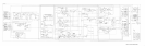
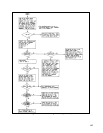
On Page 91 and on the schematic diagram Figure 6-10, change R81 to:
1.82K, 1% 1/8W Agilent P/N 0757-0429 (6030A, 6035A only)
1.78K, 1% 1/8W Agilent P/N 0757-0278 (6032A only)
On Page 92 and on the schematic diagram Figure 6-10, change R92 to:
10K, 1% 1/8W Agilent P/N 0757-0442 (6030A, 6035A only)
34.8K, 1% 1/8W Agilent P/N 0757-0123 (6031A only)
11.5K, 1% 1/8W Agilent P/N 0698-5383 (6032A only)
On Page 94, add option 100 label (A2 board) 9320-5540.
On Page 102, change front panel from:
06030-00012 to 06030-00011 (6030A)
06031-00013 to 06031-00012 (6031A)
06032-00023 to 06032-00022 (6032A)
06035-00001 to 06035-00003 (6035A)
On Page 103, add line voltage label (rear panel) Agilent P/N 06032-81004.