


74
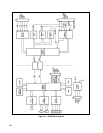
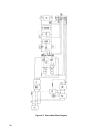
Constant Current (CC) Circuit.
The Constant Current Circuit compares the CURRENT SENSE voltage level to CC
PROGRAMMING VOLTAGE to produce CC CONTROL SIGNAL. CURRENT SENSE is developed across the
current-monitor resistor on the main board, and is proportional to the power supply output current. CC PROGRAMMING
VOLTAGE comes from one of a number of sources as selected by the rear-panel mode switches, and represents the desired
output current or current limit.
CC CONTROL SIGNAL varies from approximately -1 to +0.5 volts when the power supply is in constant current mode,
and is most positive when the CC Circuit is calling for maximum power supply output. CC CONTROL SIGNAL is
connected through an output diode, CR11, shown at the wired-OR gate that is the CONTROL PORT.
The amplified current-sense signal is brought out of the CC Circuit as I-MON (current monitor). I-MON is connected to the
rear-panel IM terminal, and varies from 0 to + 5 volts as the output current varies from zero to full scale.
A differentiator circuit in the CC Circuit block provides increased stability for highly reactive loads.
Constant Voltage (CV) Circuit. Operation of the CV Circuit is similar to the CC Circuit. The CV Circuit compares the
output SENSE voltage to the CV PROGRAMMING VOLTAGE to produce the CV CONTROL SIGNAL. + OUT and -
OUT are also supplied to the circuit as protection in case the sense leads are inadvertently disconnected. CV CONTROL
SIGNAL also varies between approximately -1 to + 0.5 volts, and is connected through diode CR24 to the CONTROL
PORT.
The buffered voltage-sense signal is brought out of the CV Circuit as V_MON (voltage monitor). V_MON is connected to
the rear-panel VM terminal, and varies from 0 to + 5 volts as the output voltage varies from zero to full scale. Both V-MON
and I-MON are referenced to monitor common ( M).
The CV Circuit also produces the
DOWN PROGRAM ENABLE signal when the CV PROGRAMMING VOLTAGE is
changed quickly from a relatively high level to a relatively low level. This allows the power supply output voltage to be
lowered more rapidly than if the output filter capacitors had to be discharged solely through the load.
CC And CV Current Sources. This circuit generates constant currents that are connected to front-panel VOLTAGE and
CURRENT potentiometers of non-- GPIB units to develop the CC and CV programming voltages.
Mode Switches. The rear-panel mode switches select the source of the CC and CV PROGRAMMING VOLTAGES. For
GPIB units, the programming voltages are supplied via the GPIB board, and are connected through mode switches B1 and
B4 to the CC and CV Circuits. For non-- GPIB units, mode switches B2, B3, and B5, B6 are closed. The CC and CV
Current Source outputs are connected through B2 and B5 to the front-panel CURRENT and VOLTAGE potentiometers,
and the voltages developed across the potentiometers are connected through B3 and B6 to the CC and CV Circuits.
Remote analog programming voltages can be supplied to the CC and CV Circuits from the rear-panel IP and VP terminals.
IP and VP are referenced to program common ( P).
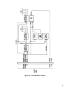
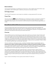
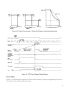
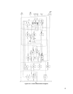
Primary Current Ramp. The output from the primary current-monitor transformer on the main board is developed across
R116 and R117 to produce a ramp voltage that represents the amount of energy being stored in the power transformer for
transfer to the power supply output circuits. This ramp voltage is connected to the Power Limit Comparator and to the
Control Voltage Comparator.
Power Limit Comparator. The power supply maximum output power curve (shown in Specifications Table in the
Operating Manual) is defined by this circuit. The PRIMARY CURRENT RAMP voltage, which represents the amount of
power being supplied to the power supply output, is compared to a voltage which represents the maximum amount of power
that the power supply can supply safely. If the ramp voltage exceeds the limit voltage, the POWER LIMIT signal is
produced to turn off the PWM.
The Power Limit Comparator Circuit includes a dynamic primary-current-limit circuit, which decreases the primary current
limit to maintain the output power curve at specified limits.