


53
An isolation transformer provides ac voltage that is not referenced to earth ground, thereby reducing the
possibility of accidentally touching two points having high ac potential between them. Failure to use an
isolation transformer as shown in Figure 3-5 will cause the ac mains voltage to be connected directly to
many components and circuits within the power supply, including the FET heatsinks, as well as to the
terminals of the external dc power supply. Failure to use an isolation transformer is a definite personal-
injury hazard.
The troubleshooting setup of Figure 3-5 connects high ac voltage to relay K1, fan B1, fuseholder A1F1, and
other components and circuits along the front of the A1 main board.
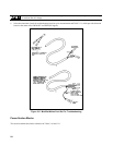
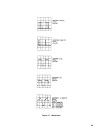
As a convenience in implementing the troubleshooting setup, modify a spare mains cord set as shown in Figure 3-6. This
facilitates connecting the unit's power receptacle to the external supply and connecting the bias transformer to the ac mains.
With the mains cord unplugged proceed as follows:
a. Remove the top cover and the inside cover per Page 35. Remove fuse A1F1.
Failure to remove fuse AlF1 will result in damage to the power supply, damage to the external dc supply,
and is an electrical shock hazard to you.
a. Install control board test connector onto the A2J7 card-edge fingers.
b. Connect a 50Ω 10-W load resistor to the unit's output terminals.
c. The external dc power supply can be connected to the unit in either of two ways (in either case, the front panel LINE
switch should be off):
1. Remove white/gray wire from main board terminal marked "N'' (at left side, just behind relay at front left
corner), and remove white/brown, gray wire from terminal "L". Connect external dc power supply to terminals
"N" and "L''. Either polarity is correct.
OR
2. Ensure that the rear-panel circuit breaker is on. Connect external dc power supply to ac input terminals ''N"
and ''L''. Either polarity is correct.
e. Complete the setup of Figure 3-5 by attaching an ac mains cord to test points J8 (L, black wire) and J7 (N, white wire)
and connect the green ground wire to the unit's case ground terminal or a suitably grounded cabinet screw. Connect the
mains cord to an isolation transformer.
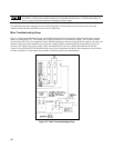
Troubleshooting No-Output Failures
No-output failures often include failure of the A4Q1, A4Q2, A4Q3, and A4Q4 PFETs and their fuses A4F1 and A4F2.
When either the off-pulses or the power-limit comparator fails, the PFETs can fail from excessive power dissipation. The
strategy for localizing no-output failures is to check the voltages and waveforms at the control board test connector to
predict if that circuit failure would cause the FETs to fail. This makes it possible to develop your troubleshooting approach
without an extensive equipment setup. Proceed as follows:
a. With the mains cord disconnected remove the A4 FET board per Page 36. Connect the mains cord and switch on
power.
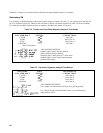
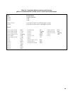
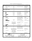
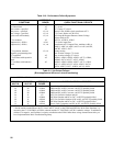
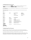
b. Using Table 3-9 check the bias voltages, the PWM-OFF and PWM-ON Control signals and other signals of interest at
the A2 control board test fingers, A2J7.
c. Check for the presence of program voltages, VP and IP, at the rear panel.
d. Check for presence of the 320Vdc rail voltage with + at the rear facing end of AlR3 and - at the rear facing end of
AlR1. If there is no rail voltage, check AlU1.