


33
3
Troubleshooting
Maintenance described herein is performed with power supplied to the instrument, and protective covers
removed. Such maintenance should be performed only by service-trained personnel who are aware of the
hazards involved (for example, fire and electrical shock). Where maintenance can be performed without
power applied, the power should be removed.
Introduction
Before attempting to troubleshoot this instrument, ensure that the fault is with the instrument itself and not with an
associated circuit. The performance test enables this to be determined without having to remove the covers from the supply.
The most important aspect of troubleshooting is the formulation of a logical approach to locating the source of trouble. A
good understanding of the principles of operation is particularly helpful, and it is recommended that Chapter 4 of this
manual be reviewed before attempting to troubleshoot the unit. Often the user will then be able to isolate a problem simply
by using the operating controls and indicators. Once the principles of operation are understood, refer to the following
paragraphs.
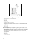
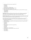
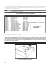
Table 2-1 lists the test equipment for troubleshooting. Chapter 6 contains schematic diagrams and information concerning
the voltage levels and waveforms at many of the important test points. Most of the test points used for troubleshooting the
supply are located on the control board test "fingers", which are accessible close to the top of the board. See Table 3-9.
If a component is found to be defective, replace it and re-conduct the performance test. When a component is replaced, refer
to Calibration Procedure (Chapter 2). It may be necessary to perform one or more of the adjustment procedures after a
component is replaced.
Initial Troubleshooting Procedures
If a problem occurs, follow the steps below in sequence:
a. Check that input power is available, and check the power cord and rear-panel circuit breaker.
b. Check that the settings of mode switch A2S1 are correct for the desired mode of operation. (See Operating Manual).
c. Check that all connections to the power supply are secure and that circuits between the supply and external devices are
not interrupted.
d. Check that the rear-panel GPIB address switch A8S1 is properly set. (See Operating Manual).
e. If the power supply fails turn-on self-test or gives any other indication of malfunction, remove the unit from the
operating system before proceeding with further testing.
Some circuits on the power mesh are connected directly to the ac power line. Exercise extreme caution
when working on energized circuits. Energize the supply through an isolation transformer to avoid
shorting ac energized circuits through the test instrument's input leads. The isolation transformer must
have a power rating of at least 4KVA. During work on energized circuits, the safest practice is to
disconnect power, make or change the test connections, and then re-apply power.
Make certain that the supply's ground terminal (
┴
) is securely connected to an earth ground before
applying power. Failure to do so will cause a potential shock hazard that could result in personal injury.