


55
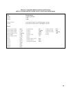
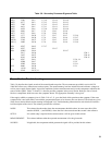
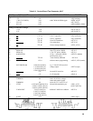
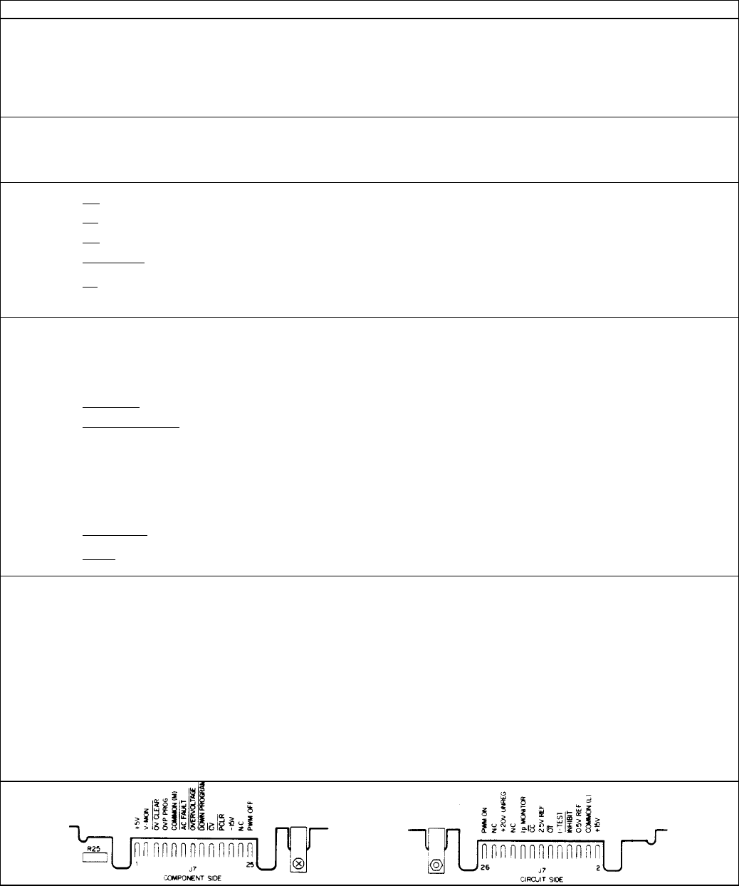
Table 3-9. Control Board Test Connector, A2J7
PIN NO. SIGNAL NAME Vdc WAVEFORM/CONDITIONS SOURCE
Digital-Circuits Bias & Reference Voltages
24 +5V 5.0 A2Q9 (emitter)
22 + 20V(5V UNREG) 20.0 with 120Hz & 45KHz ripple AlCR6, AlCR7
14 2.5V ref 2.50 A2U7 (OUT)
6 0.5V ref 0.50 A2R24,A2R84, A2R85
Analog-Circuits Bias Voltages
2 + 15V 15.0 A2U11 (OUT)
21 -15V -15.0 A2U12 (OUT )
Status Signals
17
CV
TTL Lo if in CV operation A2Q2 (collector)
16
CC
TTL Lo if in CC operation A2Q1 (collector)
13
OV
TTL Hi if not OVP shutdown A2U15-13
11
AC FAULT
TTL Hi if ac mains okay A2U15-10
12
OT
TTL Hi if not overtemp shutdown A4TS1,A5TS1
Control Signals
25 PWM OFF
10µs TTL pulses, 20KHz
A2U16-5
26 PWM ON
1.7µs TTL pulses, 20KHz
A2U15-1
18 Ip MONITOR 1V pk, ½ sawtooth, 20KHz A2CR27 (cathode)
(at full power only)
8
INHIBIT
TTL Hi if not remotely inhibited A2U18-9
15
DOWN PROGRAM
1.2-3.0 while not down programming A2CR17, CR31(anode)
7 OVP PROGRAM 1/100 OVP (6030A) e.g.: 2 Vdc if OVP set to full
1/10 OVP (6031A) voltage output A3R72 (wiper)
1/30 OVP (6032A)
1/250 OVP (6035A)
5
OV CLEAR
+5V inverted OV reset line A8U4-35
19
PCLR
+5V if +5V bias OK A2Q11-4
Commons & Current-Monitor
4 COMMON 0.0 return for all bias voltages,
status and control signals
9 COMMON 0.0 return for 2.5V and 0.5V ref
10 I-TEST
≈0.013*I0UT(6030A/35A).
inboard-side monitoring res A1R11,A1T2
≈0.0017* IOUT (6031A)
(AlR13 (6032A))
≈0.0037* IOUT (6032A)
3 V-MON-BUF V-OUT/4 (6031A) buffered V-MON for readback A8U25-6
V-OUT/12 (6032A)
V-OUT/40 (6030A)
V-OUT/100 (6035A)
20 Ip-SET
≈0.9
A2R25 wiper