


72
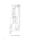
Input Circuits
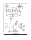
. Primary power is connected through the AC Input Filter to the LINE switch and to the normally open
contacts of the Inrush-Limit relay. When LINE switch is closed, current flows through the inrush current limiting resistor
and the normally closed relay contacts to the Bridge Rectifier/Voltage Doubler. This circuit is jumper connected as a
voltage doubler for 100 or 115Vac operation and as a full-wave bridge charges to about 320Vdc for any input voltage.
Current also flows through the Voltage Select Switch to the Bias Power Supplies, which provide the operating voltages for
the power supply. The Voltage Select Switch connects the primary windings of the bias transformer for operation at 100,
120, 220, or 240Vac. The Voltage Select Switch also supplies 120 Vac to the fan and Relay Circuits.
The Inrush Limit relay is energized by
RELAY ENABLE , which is generated on the control board after the unit has
checked that various operating voltages are within acceptable limits. After a delay of approximately 2-1/2 seconds, which
allows the Input Filter capacitors to charge, the relay is energized, bypassing the Inrush Limit resistor. A switch on the main
board switches in more Inrush Limit resistance for 220 or 240Vac operation.
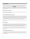
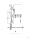
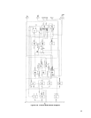
DC To DC Conversion. Current flow from the input rails through the power transformer is controlled by FET switches. On
and off pulses for the FETs are generated on the control board, as will be described shortly. On pulses are applied through
the On Driver and pulse transformer T1 to the gates of both pairs of FETs. Although the on pulse is only about 1.7
µs
duration, the FETs' input capacitance holds the FETs on after the on pulse has disappeared.
When the FETs are turned on, current flows through the primaries of Power Transformer T2 and Primary-Current Monitor
Transformer T1. The Output Diodes are reverse biased and block current flow in the T2 secondary. Consequently, energy is
stored in the field that builds around the T2 transformer windings. The longer that voltage is applied to the primary, the
more energy is stored. Current flow in the secondary of T1 is connected to the control board, where it generates a ramp
voltage. The amplitude of this linearly increasing voltage corresponds to the amount of current flow through the T2 primary;
therefore, it represents the amount of energy being stored in the field around T2. It is this ramp voltage that is compared to a
control voltage to determine when the FETs should be turned off.
Off pulses turn on Q5 and Q6, which discharge the FET gates, thereby turning the FETs off. When the FETs are turned off,
the collapsing magnetic field reverses the polarity across the T2 primary and secondary, and current flows from T2
secondary through output diodes to charge the output filter capacitors. The level to which the output capacitors are charged
corresponds to the length of time that the FETs are on and current flows in T2 primary.
Leakage inductance of T2 attempts to maintain current flow in the primary circuit when the FETs turn off. Flyback diodes in
the FET board protect the FETs by conducting this current around the FETs and back to the input filter.
Down Programmer. This circuit allows the output voltage to be lowered rapidly when required. In order to lower the
output voltage it is necessary to discharge the output filter capacitors (typically, through the load). In situations that require
the output voltage to drop more rapidly than can be accomplished through the load, the Down Programmer discharges the
capacitors and pulls the output line low.
DOWN PROGRAM ENABLE is generated on the control board. Six conditions
can conditions can trigger down programming: programming of a lower output voltage, overvoltage, overtemperature,
remote disable, remote inhibit, or primary power failure.
The + 10.6Vdc bias supply for the Down Programmer stores enough energy in its input capacitor to operate the Down
Programmer after loss of primary power. This ensures that the Down Programmer will be able to discharge the output
circuit completely when primary power is turned off.
The Agilent 6030A/35A units contain an active bleed circuit, connected across the output, which allows regulation at low
output current and/or low output voltage levels. This circuit also minimizes dielectric absorption effects, which show up as
noise on the output of the supply.
Current Monitor Resistor. A highly stable resistance element in the -output line develops the CURRENT SENSE voltage,
which is proportional to the power supply output current. This signal is supplied to the CC Circuit on the control board.