


26
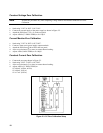
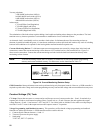
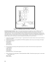
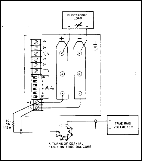
Figure 2-6. RMS Measurement Test Setup, CV PARD Test
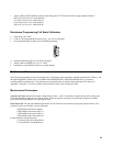
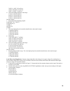
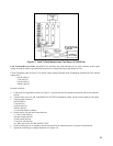
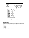
Peak Measurement Procedure. Figure 2-7 shows the interconnections of equipment to measure PARD in Vpp. The
equipment grounding and power connection instructions of Paragraph 2-36 apply to this setup also. Connect the
oscilloscope to the + S and - S terminals through 0.01µF blocking capacitors to protect the oscilloscope's input from the
unit's output voltage. To reduce common-mode noise pickup, set up the oscilloscope for a differential, two-channel voltage
measurement. To reduce normal-mode noise pickup, use matched-length, 1 meter or shorter, 50Ω coaxial cables with
shields connected to the oscilloscope case and to each other at the other ends. Proceed as follows:
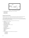
a. Connect the test equipment as shown in Figure 2-7. Operate the load in constant resistance mode (Amps/Volt) and set
resistance to maximum.
b. Turn the unit's power on, and, using DISPLAY SETTINGS pushbutton switch, turn up current setting to full output.
c. Turn up output voltage to:
60Vdc (6030A)
7Vdc (6031A)
20Vdc (6032A)
200 Vdc (6035A)
d. Turn up output current setting to full output and reduce the resistance of the load to draw an output current of:
17.0Adc (6030A)
120Adc (6031A)
50Adc (6032A)
5.0Adc (6035A)
Check that the unit's CV LED remains lighted.
e. Set the oscilloscope's input impedance to 50Ω and bandwidth to 20MHz. Check that the peak-to-peak is no more than:
50mV (6030A/31A)
40mV (6032A)
160mV (6035A)