


60
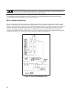
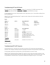
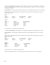
+15V On A2 Control Board. Voltage regulator A2U11 regulates the voltage across resistor A2R99 to be 1.25Vdc. That
sets the current through zener diode A2VR3 at 7.5mAdc. The output voltage is 1.25Vdc plus 11.7Vdc across A2VR3 plus
the voltage across A2R100.
Circuit Included. +15Vdc bias supply circuitry from connector pin A2J5-5 through test point A2J7-2 on A2 control board.
Setup. The Main Troubleshooting Setup, Page 53. Apply the ac mains voltage to the isolation transformer, and set the
external supply to 0Vdc.
Input:
NODE (+) NODE (-) MEASUREMENT SOURCE
A2C52 (+) A2C52 (-)
≈ + 25Vdc
A1U4
Outputs:
NODE ( + ) NODE (-) MEASUREMENT
A2J7-2 A2U11-3 (ADJ) l.25Vdc
A2J7-2 A2VR3 (anode) 12.9Vdc
A2J7-2 A2VR3 (anode) 6.2Vdc
A2C50( + ) A2C50( - ) 13.8Vdc
To check if load on +15V is shorted, remove jumper A2W1.
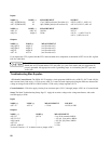
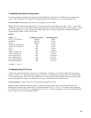
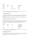
-15 V On A2 Control Board. Voltage regulator A2U12 regulates the voltage across resistor A2R103 to be 1.25Vdc.
Circuit Included. -15 Vdc bias supply circuitry from connector pin A2J5-6 through test point A2J7-21 on A2 control
board.
Setup. The Main Troubleshooting Setup, Page 53. Apply the ac mains voltage to the isolation transformer, and set the
external supply to 0Vdc.
Input:
NODE (+) NODE (-) MEASUREMENT SOURCE
A2C55 (+) A2C55 (-)
≈ - 25Vdc
A1U4
Outputs:
NODE ( + ) NODE (-) MEASUREMENT
A2J7-21 A2U12-3 (ADJ) - l.25Vdc
A2J7-21 A2VR4 (cath) - 12.9Vdc
A2C54( + ) A2C54( - ) 13.8Vdc
To check if load on -15V is shorted, remove jumper A2W2.
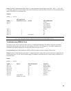
Refer to Down Programmer, for the + 10.6Vdc bias supply, and refer to OVP Circuit, for the + 2.5V bias supply.