


51
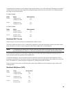
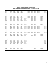
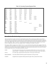
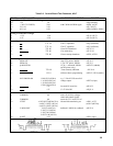
Table 3-8. Secondary Processor Signature Table
DS(0) P36U U4-1 U7-15 U9-15 U11-15
DS(1) 2280 U4-2 U7-14 U9-14 U11-14
DS(2) 4277 U4-3 U7-13 U9-13 U11-13
DS(3) 720F U4-4 U7-12 U9-12 U11-12
DS(4) 6A31 U4-5 U7-11 U9-11 U11-11
DS(5) 662U U4-6 U7-10 U9-10 U11-10
DS(6) 6020 U4-7 U7-9 U9-9 U11-9
DS(7) 6327 U4-8 U7-8 U9-8 U11-8
DS(8) 1377 U4-39 U7-7 U9-7 U11-7 U2-16
DS(9) FF99 U4-38 U7-6 U9-6 U11-6 U2-17
DS(10) 236P U4-37 U7-5 U9-5 U11-5 U2-18
DS(11) H495 U4-36 U7-4 U9-4 U11-4 U2-19
WR* 9FU7 U4-12 U7-17
WR* 9FF7 U4-13 U9-17
WR* 9FHU U4-14 U11-17
F817 U4-26 U20-1
36U7 U4-27 U20-16
0562 U4-28 U20-15
ISTX 9F97 U4-11 U2-4, 14
9FH6 U4-17 U2-2
9FH5 U4-16 U2-11
ALE 0000 U4-30 U2-1
AU68 U4-35
+ 5V 9FA8 U4-33,34
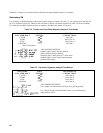
Power Section Troubleshooting
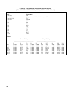
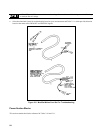
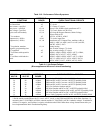
Table 3-9 describes the signals at each of the control board test points. The test connector provided in service kit P/N
5060-2865 allows easy connection to each test point. The measurements given here include bias and reference voltages as
well as power supply status signals. It provides conditions for these measurements and gives the components which are the
sources of the signals. Tables 3-10 and 3-11 describe possible symptoms in the power section. Both give lists of circuit
blocks or components which can cause the symptoms shown. The appropriate assembly is also given.
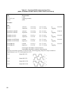
If the supply exhibits a symptom given in Table 3-10 or 3-11, go to the block which pertains to that symptom. If the exact
symptom seen is not in the tables, start with the symptom that seems to be closest to the one observed. The blocks are given
in the Power Section Blocks section starting in Paragraph 3-84. Troubleshooting information for each block will include a
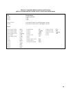
brief description of the circuit. The columns provided are as follows:
NODE: This column lists the nodes where the measurements should be taken. In some cases this will be
stated as NODE( + ) and NODE(-) where the first is the test node and the second is the reference.
SETUP: If a certain setup is required for the measurement, it will be given in this column.
MEASUREMENT: This column indicates what the expected measurement is for the given node.
SOURCE: If applicable, the components which generate the signal will be provided in this column.