


126
Chapter 3 Manual Changes:
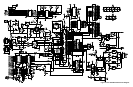
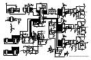
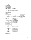
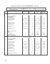
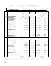
Replace Figure 3-1 with the figure on the next page. SA Tables 3-5 through 3-7 do not apply to Option 001 units.
Chapter 5 and 6 Manual Changes:
On Page 94 under A3 Front Panel Board, the only part that applies to the Option 001 unit is R72, the OVP-adjust
potentiometer. Change R72 from 2100-1775 to 2100-4060.
On Page 102 under Chassis Electrical, add Neon Pilot Light, P/N 1450-0647. Also add OVP Cable (R72), P/N 06032-
60004. Under Chassis Mechanical, change screened front panel to:
06030-00010 (6030A)
06031-00011 (6031A)
06032-00021 (6032A)
On Figure 6-9, add the neon pilot light in series with R8, 33K, across pins 4 and 5 of transformer T3.
On Figure 6-12, the only part that applies to the Option 001 unit is R72, the OVP-adjust potentiometer.