


20
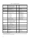
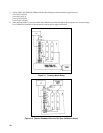
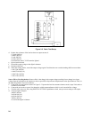
Power Limit Calibration
Note: This procedure requires that CC PROG F. S. (A8R55) be adjusted within specifications. If it is not,
perform Constant Current Full Scale Calibration before proceeding.
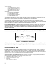
a. Connect the power supply to the ac power line through a variable autotransformer. Connect a DVM across the input
power rails, with the + lead to the rear of A1R3 and the - lead to the rear of A1R1. Adjust the autotransformer for
240Vdc on the input power rail. The input power rail must be maintained at 240Vdc during calibration.
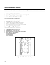
The top inside cover must be removed to connect the DVM. Disconnect the ac mains power cord before
connecting or disconnecting the DVM.
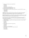
a. Connect a electronic load across the output terminals, or use a:
3.8 ohm 1500W resistor (6030A)
0.066 ohm 1500W resistor (6031A)
0.44 ohm 1500 W resistor (6032A)
39 ohm 1500 W resistor (6035A)
b. Set the electronic load for:
17 amperes (6030A)
120 amperes (6031A)
51 amperes (6032A)
5 amperes (6035A)
in the constant Current mode.
c. Turn A2R25 (LOWER KNEE) fully counterclockwise.
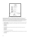
d. Turn on power supply and send string:
"VSET 65; ISET 17.4; OUT ON" (6030A)
''VSET 8; ISET 121; OUT ON'' (6031A)
"VSET 22; ISET 51; OUT ON" (6032A)
''VSET 200; ISET 5.1; OUT ON'' (6035A)
e. Adjust A2R25 (LOWER KNEE) clockwise until CV LED on front panel turns on. Power supply output should be:
65 ±0.2V @17A in CV mode (6030A)
8 ±0.08V @120A in CV mode (6031A)
22 ±0.2V @50A in CV mode (6032A)
200 ±0.5V @5A in CV mode (6035A)
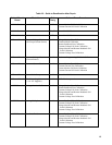
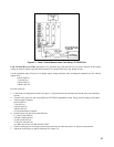
f. Turn off power supply. Reset the electronic load for:
5.25A in CC mode (6030A)
51A in CC mode (6031A)
18.2A in CC mode (6031A)
2.2A in CC mode (6035A)
or change the resistor to:
38ohm 1500W (6033A)
0.4ohm 1500W (6031A)
3.3ohm 1500W(6032A)
227ohm 1500W(6035A)
g. Turn A2R26 (UPPER KNEE) fully counterclockwise.
h. Turn on power supply. Send string
"VSET 200; ISET 5.5; OUT ON" (6030A)
"VSET 20.5; ISET 55; OUT ON" (6031A)
"VSET 60; ISET 19; OUT ON" (6032A)
"VSET 500; ISET 2.2; OUT ON" (6035A)