


45
Signature Analysis
Perform the signature analysis only after you have completed the Primary Processor Troubleshooting.
The easiest and most efficient method of troubleshooting microprocessor-based instruments is signature analysis. Signature
analysis is similar to signal tracing with an oscilloscope in linear circuits. Part of the microcomputer memory is dedicated to
signature analysis and a known bit stream is generated to stimulate as many nodes as possible within the circuit. However,
because it is virtually impossible to analyze a bit stream with an oscilloscope, a signature analyzer is used to compress the
bit stream into a four-character signature that is unique for each node. By comparing signatures of the unit under test to the
correct signatures for each node, faults can usually be isolated to one or two components. Note that signature analysis
provides only go/no-go information; the signature provides absolutely no diagnostic information.
The following general notes apply to signature analysis of the power supply.
1. Be certain to use the correct setup for the signature being examined.
2. Most signatures are taken on the GPIB, and front panel assemblies.
3. Note the signatures for Vcc and ground on the I.C. being examined. If an incorrect signature is the same as that of Vcc
or ground, that point is probably shorted to Vcc or ground.
4. If two pins have identical signatures, they are probably shorted together. If two signatures are similar, it is only
coincidence. For example, if the signature at a certain point should be 65C4, a signature of 65C3 is not "almost right".
No diagnostic information can be inferred from an incorrect signature.
5. If a signature is incorrect at an input pin, but is correct at its source (output of previous I.C.), check for printed circuit
and soldering discontinuity.
6. An incorrect signature at an output could be caused by a faulty component producing that output; or, a short circuit in
another component or on the board could be loading down that node.
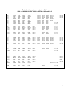
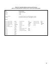
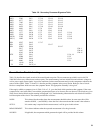
Tables 3-2 and 3-3 show the primary, front panel, and secondary signature analyzer connections that are required to perform
the SA tests in Tables 3-4 through 3-8. Remember that the primary and secondary circuits each reference a different circuit
common.
Primary SA
Place the unit in primary SA mode by moving the J5 jumper as shown in Table 3-2. Connect the signature analyzer as
shown in the table. The front panel display should indicate: ''SA SA", and all LED's will be on. If the display is different,
replace U14.
Note: The power supply will not go into SA mode if one of the data and address lines is shorted either high or
low. Refer to Data Lines troubleshooting.
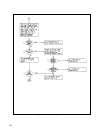
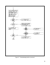
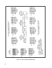
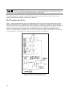
When the unit is in SA mode, check for the waveforms shown in Figure 3-3. Refer to Table 3-4 for the primary SA
signatures. Return the J5 jumper to its normal position when the primary signature analysis is complete.
Front Panel SA
To place the unit in SA mode for Front Panel SA troubleshooting, follow the procedure for Primary SA troubleshooting.
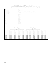
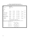
When the unit is in SA mode, check the signatures in Tables 3-5 through 3-7.
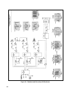
The signatures in Table 3-5 check the registers that drive the 7-segment LED displays. Most problems will involve only one
display or LED indicator. Table 3-6 checks the address latches and decoders. Address latch U15 forwards address data to
the address decoders, which enable the shift registers. Table 3-7 checks flip-flop U12, shift register U11, and gate U18. U12
decodes the output of the RPG. U11 and U18 are used by the microprocessor to read the status of the RPG and front panel
switches.