


56
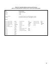
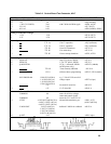
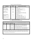
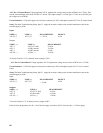
Table 3-10. Performance Failure Symptoms
DEFECTIVE
SYMPTOMS BOARD CHECK FUNCTIONAL CIRCUITS
unexplained OVP shutdowns A2 OVP circuit, CV circuit
no current limit A2 CC circuit
max current < specified A2 CC Clamp, CC circuit
max power < specified A2, A1 Power Limit, 20KHz clock, transformer AlT1
max voltage < specified A2, A1 CV Circuit, diodes A1CR1-CR4
cycles on & off randomly A2, A1 AC-Surge-&-Dropout Detector, Mains Voltage
Select switch A1S2
CV overshoots A2 A2U5A, A2CR19, A2R62
output noise (<1KHz) A2,A1 CV circuit, input filter
output noise (>1KHz) A1, A4 transformer AlT2, Output Filter, snubbers A4R1 to
A4R11, A4R13 to A4R19, A4C1 to A4C4, A4CR2,
A4CR3, A2R15, A2C2
CV regulation, transient A2, A1 wrong sensing
response, programming time low ac mains voltage, CV circuit
CC regulation A2 low ac mains voltage, CC circuit
CV oscillates with capacitive A2 A2R61, A2R60, A2R58, A2R59, A2C33, A2R64,
loads A2R68, A2C36, A2C37, A2U5, A2R65
CC oscillates with inductive A2 A2R61, A2R60, A2R58, A2R57, A2C33, A2R19
loads A2C11, A2R28, A2C12, A2U4, A2R35, A2C20,
A2U4, A2R37, A2C17, A2R29, A2C18, A2R31
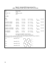
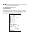
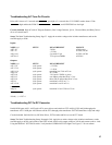
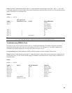
Table 3-11. No-Output Failures
(Bias supplies and AC turn-on circuit functioning)
Status of FET On/Off-Pulses
PWM-ON
A2J7-26
PWM-OFF
A2J7-25
DEFECTIVE
BOARD
CHECK FUNCTIONAL CIRCUITS
Lo Lo A2 Control ckts: CV & CC thru On- & Off-Pulse Oneshots *
Lo Hi A2&A4 PWM and DC-to-DC Converter: A4 PFETS probably failed
Hi Lo A2&A4 PWM and DC-to-DC Converter: A4 PFETS probably failed
Hi Hi A2&A4 PWM and DC-to-DC Converter: A4 PFETS probably failed
Lo N A2 A2U15A, On-Pulse Oneshot and Q11
N Lo A2&A4 Off-Pulse Oneshot and DC-to-DC: A4 PFETS probably failed
Hi N A2&A4 A2U15A, On-Pulse Oneshot & DC-to-DC: A4 PFETS probably failed
N Hi A2&A4 Off-Pulse Oneshot and DC-to-DC: A4 PFETS probably failed
N N A2&A4 Power-Limit Comparator and DC-to-DC: A4 PFETS probably failed
Lo= TTL low Hi= TTL high N= normal 20KHz pulse train, TTL levels
* Decide which to troubleshoot--the CV circuit, the CC circuit, or the PWM and Off-Pulse & On-Pulse Oneshots-- by
measuring the CV CONTROL (A2CR24, cathode) and the CC CONTROL (A2CR11 cathode) voltages. Troubleshoot
whichever is negative, and if neither is negative, troubleshoot the PWM. Make these voltage measurements after you
have implemented the Main Troubleshooting Setup.