


46
Return the J5 jumper to its normal position when the front panel signature analysis is complete.
Secondary SA
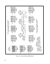
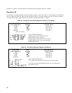
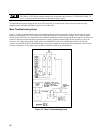
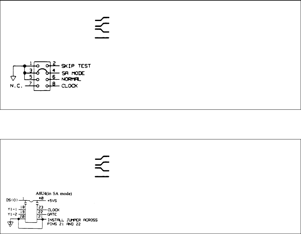
For secondary SA troubleshooting, connect the signature analyzer as shown in Table 3-3. Use a jumper wire and short U4
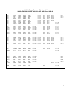
pin 21 to common (U4 pin 20). Check for the waveforms in Figure 3-4 and the signatures in Table 3-8 for the secondary
SA. When the secondary signature analysis is complete, disconnect the jumper on U4 pin 21.
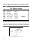
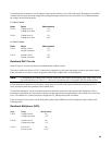
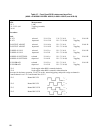
Table 3-2. Primary and Front Panel Signature Analyzer Test Setups
SIGNATURE
ANALYZER INPUT
EDGE
SETTING
PRIMARY SA
CONNECTIONS
CLOCK
START
STOP
GROUND
A8J5 pin 8
A8U37 pin 16
A8U37 pin 16
A8J5 pin 5
A8J5 (in SA mode)
A8J5 JUMPER POSITIONS
Jumpering pins 1 and 2 skips the internal
selftest when the unit is turned on.
Jumpering pins 3 and 4 places U37 in SA mode.
Jumpering pins 5 and 6 is the normal/operating
position of the jumper.
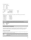
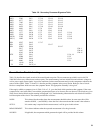
Table 3-3. Secondary Signature Analyzer Test Setups
SIGNATURE
ANALYZER INPUT
EDGE
SETTING
SECONDARY SA
CONNECTIONS
CLOCK
START
STOP
GROUND
A8U4 pin 23
A8U4 pin 22
A8U4 pin 22
A8U4 pin 20
A8U4 JUMPER POSITIONS
Use a jumper wire and connect A8U4 pin 21 to pin 20 (ground).
Use a 40-pin test clip (Pomona Model 5240 or eq.) to facilitate test
connections to A8U4.