


68
Front Panel Board
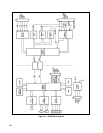
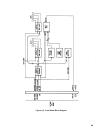
The front-panel board, see Figure 4-2, contains the VOLTS and AMPS display circuits, the rotary pulse generator (RPG)
and RPG decoders, five pushbutton switches, mode indicators, and the OVP ADJUST potentiometer. Data from the
microprocessor is shifted to the display circuits via
DATA DOWN , and data from the front-panel controls circuits is
shifted to the microprocessor via DATA UP. Circuits on the front-panel board operate from bias voltages supplied from the
GPIB board, and are referenced to the same common as the GPIB board (earth ground). The OVP ADJUST potentiometer
is part of the power mesh control circuitry (referenced to power supply negative output), and is not connected to any circuits
on the front-panel board.
Address Latches and Decoders
DATA DOWN bits received while D / A is low are latched and decoded in this circuit, which then steers clock pulses to
the addressed circuit when
D / A goes high.
Volts and Amps Output Ports and Displays
These circuits display values sent by the microprocessor via DATA DOWN. Normally, these are the actual output voltage
and current readings. Pressing the DISPLAY SETTINGS switch causes the microprocessor to send the voltage and current
values that have been sent by the controller (remote) or RPG (local). If the unit is in CV mode, the voltage display should
show the same reading for actual and set values; the current display will switch from the actual value to the current limit. In
CC mode, the current readings will be the same and the voltage display will switch from actual value to the voltage limit.
Pressing the DISPLAY OVP switch causes the voltage display to show the OVP trip voltage that has been set.
The microprocessor also uses the readout to display the GPIB address switch settings, self test error messages, and readback
overrange conditions.
RPG and Latches
When rotated, the RPG products two pulse trains that are 90 degrees phase shifted from each other, with the phase
relationship determined by the direction of rotation. This circuit contains two flip-flops that monitor the RPG outputs. The
output of one flip-flop goes low to indicate that the RPG has been rotated, and the output of the other goes low to indicate
CW rotation or high to indicate CCW rotation. This data is loaded into an input port when
D / A is low, and the flip-flops
are set back to their quiescent state by clock pulses from the address decoder when the input port is addressed.
Because the microprocessor reads the input approximately every millisecond, it can determine if the RPG is being turned
rapidly (for a large change) or slowly (for fine adjustment), and the microprocessor varies the rate it changes the DAC
inputs accordingly.
Front-Panel Switches and Input Port
Five front-panel pushbutton switches plus the two RPG flip-flop outputs are connected to this input port. Data is loaded
when
D / A is low, and is shifted out by clock pulses from the address decoders. The microprocessor reads data in via
DATA UP approximately every millisecond, and checks the switches every 10 ms, thereby ensuring that even rapid switch
operations will be captured.