


24
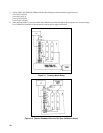
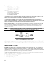
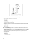
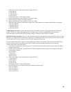
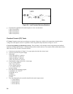
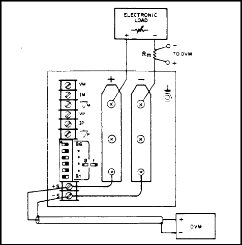
Figure 2-5. Basic Test Setup
d. Reduce the resistance of the load to draw an output current of:
17.0Adc (6030A)
120Adc (6031A)
50 Adc (6032A)
5.0 Adc (6035A)
Check that the unit's CV LED remains lighted.
e. Open-circuit the load.
f. Record the output voltage at the digital voltmeter.
g. Reconnect the load.
h. When the reading settles, record the output voltage again. Check that the two recorded readings differ no more than:
± 0.011Vdc (6030A)
± 0.0037Vdc (6031A)
± 0.007 Vdc (6032A)
± 0.033 Vdc (6035A)
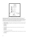
Source Effect (Line Regulation). Source effect is the change in dc output voltage resulting from a change in ac input
voltage from the minimum to the maximum value as specified in Input Power Requirements in the Specifications Table, in
the Operating Manual. Proceed as follows:
a. Connect the test equipment as shown in Figure 2-5. Operate the load in constant resistance mode (Amps/Volt) and set
resistance to maximum.
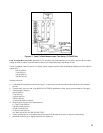
b. Connect the unit to the ac power line through a variable autotransformer which is set for nominal line voltage.
c. Turn the unit's power on, and, using DISPLAY SETTINGS pushbutton switch, turn up current setting to full output.
d. Turn up output voltage to:
200Vdc (6030A)
20.0Vdc (6031A)
60.0Vdc (6032A)
500Vdc (6035A)
as read on the digital voltmeter.