


5-5
Cisco ASR 903 Router Hardware Installation Guide
OL-25178-04
Chapter 5 Troubleshooting
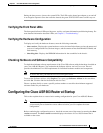
Pinouts
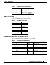
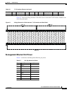
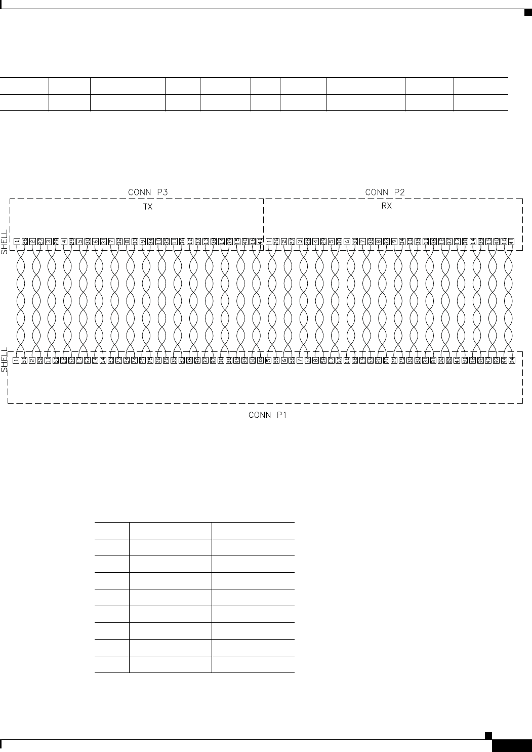
Figure 5-1 shows the wiring schematic of the cable used to connect the T1/E1 interface module to the
rear of the patch panel.
Figure 5-1 Wiring Schematic of Cable between T1/E1 Interface and Patch Panel
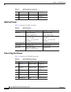
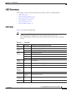
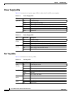
Management Ethernet Port Pinout
Table 5-7 summarizes the Management Ethernet port pinout.
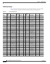
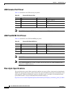
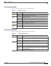
Line 15 100 TX_RING_P5 41 1 94 RX_RING_P5 41 4
50 TX_TIP_P5 16 2 44 RX_TIP_P5 16 5
Table 5-6 T1/E1 Interface Pinouts (continued)
343344
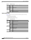
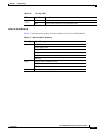
Table 5-7 Fan Tray Alarm Port Pinout
Pin Signal Name Description
1TRP0+
2TRP0-
3TRP1+
4TRP2+
5TRP2-
6TRP1-
7TRP3+
8TRP3-