


3-42
Cisco ASR 903 Router Hardware Installation Guide
OL-25178-04
Chapter 3 Installing the Cisco ASR 903 Router
Connecting the Cisco ASR 903 Router to the Network
ports as described in GR-1089-CORE) and require isolation from the exposed OSP cabling. The
addition of Primary Protectors is not sufficient protection in order to connect these interfaces
metallically to OSP wiring.
Recommended Patch Panel
We recommend the following T1/E1 patch panels:
48-port T1 RJ45 patch panel (part number DCC4884/25T1-S)
16-port E1 BNC patch panel (part number DCC16BNC/25T1-S)
The patch panels are available from Optical Cable Corporation (http://www.occfiber.com). To order a
patch panel, contact the Sales and Marketing Support staff at Optical Cable Corporation:
• 800-622-7711 (toll-free in the U.S.A.)
• 540-265-0690 (outside the U.S.A.)
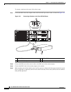
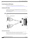
Connecting the Fan Tray Alarm Port
The fan tray includes an alarm port that maps to 4 dry contact alarm inputs.
The pins on the alarm port are passive signals and can be configured as Normally Open (an alarm
generated when current is interrupted) or Normally Closed (an alarm is generated when a circuit is
established) alarms. You can configure each alarm input as critical, major, or minor. An alarm triggers
alarm LEDs and alarm messages. The relay contacts can be controlled through any appropriate
third-party relay controller. The open/close configuration is an option controlled in IOS.
Warning
To comply with the Telcordia GR-1089 NEBS standard for electromagnetic compatibility and safety,
connect the alarm ports only to intra-building or unexposed wiring or cable. The intrabuilding cable
must be shielded and the shield must be grounded at both ends. The intra-building port(s) of the
equipment or subassembly must not be metallically connected to interfaces that connect to the OSP
or its wiring. These interfaces are designed for use as intra-building interfaces only (Type 2 or Type 4
ports as described in GR-1089-CORE) and require isolation from the exposed OSP cabling. The
addition of Primary Protectors is not sufficient protection in order to connect these interfaces
metallically to OSP wiring.
Only Pins 1, 2, 4, 6, and 8 are available for customer use. The remaining pins are for Cisco manufacturing
test, and should not be connected. Use a shielded cable for connection to this port for EMC protection.
Table 5-4 summarizes the pinouts on the alarm port in Chapter 5, “Troubleshooting.”
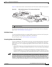
Step 1 Attach an RJ45 cable to the alarm port.
Step 2 Attach the other end of the RJ45 cable to the relay controller.
For information about how to map alarm inputs to critical, major, and minor alarm conditions, see the
Cisco ASR 903 Router Software Configuration Guide.