


2-21
Cisco ASR 903 Router Hardware Installation Guide
OL-25178-04
Chapter 2 Preparing for Installation
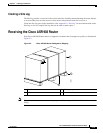
Receiving the Cisco ASR 903 Router
Note For more information on cable specifications, see Chapter 5, “Troubleshooting.”
• Ethernet hub or switch or PC with a network interface card for connecting to the Ethernet ports
• Console terminal (an ASCII terminal or a PC running terminal emulation software) that is
configured for 9600 baud, 8 data bits, no parity, and 2 stop bits
• Console cable for connecting to the console port
• (Optional) Modem for connecting to the auxiliary port for remote administrative access
• Auxiliary cable for connecting to the auxiliary port (you can supply this cable or order one)
• Ratcheting torque screwdriver with a Phillips head that exerts up to 30 pound-force per square inch
(in-lb) of pressure
• Crimping tool as specified by the ground lug manufacturer
• 18 AWG copper wire for the power cord
• Wire-stripping tools for stripping both 6 AWG and 18 AWG wire
• Tape measure and level
Warning
Only trained and qualified personnel should be allowed to install or replace this equipment.
Statement 49
Unpacking and Verifying the Shipped Contents
When you receive your chassis, perform the following steps and use the Shipping Contents Checklist:
Step 1 Inspect the box for any shipping damage. If there is obvious physical damage, contact your Cisco service
representative.
Step 2 Unpack the Cisco ASR 903 Router.
Step 3 Perform a visual inspection of the chassis.
Step 4 Use Table 2-2 to check the contents of the Cisco ASR 903 Router shipping container. Do not discard the
shipping container. You will need the container if you move or ship the Cisco ASR 903 Router in the
future.
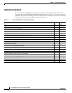
Table 2-2 Cisco ASR 903 Router Shipping Container Contents
Component Description
Chassis Cisco ASR 903 Router chassis
Fan tray
Power supplies
RSP
Interface modules