


3-41
Cisco ASR 903 Router Hardware Installation Guide
OL-25178-04
Chapter 3 Installing the Cisco ASR 903 Router
Connecting the Cisco ASR 903 Router to the Network
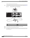
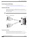
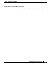
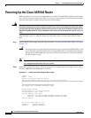
Figure 3-26 shows how the cable is connected between the T1/E1 interface module and the patch panel.
Figure 3-26 Cable Installation between T1/E1 Interface and Patch Panel
For information about the pinout of the cable connecting the T1/E1 interface to the rear of the patch
panel, see the “T1/E1 Port Pinout” section on page 5-4.
RJ45 Cable Pinouts
T1 lines from individual subscribers are attached to RJ45 connectors on the front of the 24-port patch
panel. Each RJ45 port accommodates an individual T1 subscriber line.
For the T1/E1 ports, see the “T1/E1 Port Pinout” section on page 5-4.
Connecting Cables to the Patch Panel
If you are connecting two T1/E1 interfaces to each other, you must cable both interfaces’ patch panels
together using a T1 cross-over cable or a T1 straight-through cable. Use shielded cables. The type of
cable you use (cross-over or straight-through) depends on how the T1/E1 interfaces are cabled to their
patch panels:
• If both T1/E1 interfaces are connected to their patch panels in the same manner (TX to Transmit and
RX to Receive, or TX to Receive and RX to Transmit), use a T1 cross-over cable to connect the patch
panels.
• If both T1/E1 interfaces are connected to their patch panels in a different configuration (TX to
Transmit and RX to Receive on one interface, and TX to Receive and RX to Transmit on the other
interface), use a T1 straight-through cable (standard RJ45 patch cable) to connect the patch panels.
Warning
To comply with the Telcordia GR-1089 NEBS standard for electromagnetic compatibility and safety,
connect the T1/E1 ports only to intra-building or unexposed wiring or cable. The intrabuilding cable
must be shielded and the shield must be grounded at both ends. The intra-building port(s) of the
equipment or subassembly must not be metallically connected to interfaces that connect to the OSP
or its wiring. These interfaces are designed for use as intra-building interfaces only (Type 2 or Type 4
1 Patch panel interfaces
255735
TRANSMIT
RECEIVE
PORTS 1-16
1