


5-9
Cisco ASR 903 Router Hardware Installation Guide
OL-25178-04
Chapter 5 Troubleshooting
LED Summary
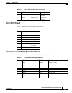
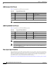
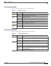
OC-3 Interface Module LEDs
Table 5-13 summarizes the LEDs for the OC-3 interface module.
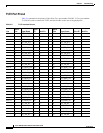
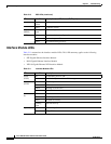
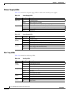
T1/E1 Interface Module LEDs
Table 5-13 summarizes the LEDs for the T1/E1 interface module.
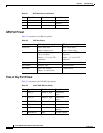
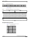
Table 5-12 Interface Module LEDs
LED Color/State Description
Power
(PWR)
Off Disabled/no power to IM
Green Enabled and power rails on IM in range
Status
(STAT)
Off Disabled/power-down
Red Failure (on at reset)
Amber Booting (if local CPU)
Green Operational
Carrier/
Alarm (C/A)
Green SFP receiving good remote signal
Yellow Remote or local alarm activated
Active/
Loopback
(A/L)
Green SFP ready and operating normally
Yellow SFP port in loopback state
Table 5-13 T1/E1 Interface Module LEDs
LED Color/State Description (two LEDs for eachT1/E1 port)
Active Green Active
Blinking
green
Standby
Off Operationally down; card is disabled or shut down
Port Green All ports up
Blinking
green
All ports up and one or more ports in a loopback state
Amber One or more configured ports are down
Blinking
amber
One or more configured ports are down and at least one configured port
is in a loopback state
Off All ports disabled or shut down