3-5
Cisco ASR 903 Router Hardware Installation Guide
OL-25178-04
Chapter 3 Installing the Cisco ASR 903 Router
Installing the Chassis Ground Connection
Installing the Chassis Ground Connection
Before you connect the power or turn on the power to the Cisco ASR 903 Router, you must provide an
adequate chassis ground (earth) connection to your router.
This section describes how to ground the Cisco ASR 903 Router chassis. The router provides two
locations for attaching a 2-hole grounding lug according to the rack-mounting brackets you use to install
the router. The Cisco ASR 903 Router supports the following rack-mounting types:
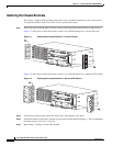
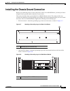
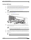
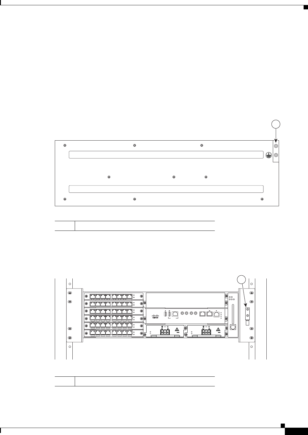
• EIA 19-inch rack—Attach the grounding lug to the rear of the router, as shown in Figure 3-7.
Figure 3-7 Attaching a Grounding Lug to the Rear of the Router
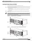
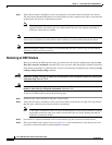
• 300 mm ETSI cabinet—Attach the grounding lug on the rack-mount bracket on the front of the
router, as shown in Figure 3-8.
Figure 3-8 Attaching a Grounding Lug to the Rack-Mount Bracket
1 Grounding lug (19-inch EIA rack)
281928
1
1 Grounding lug (300 mm ETSI cabinet)
281929
GE-0 GE-1 GE-2 GE-3 GE-4 GE-5 GE-6 GE-7
PWR
STAT
GE-0 GE-1 GE-2 GE-3 GE-4 GE-5 GE-6 GE-7
PWR
STAT
GE-0 GE-1 GE-2 GE-3 GE-4 GE-5 GE-6 GE-7
PWR
STAT
PWR
STAT
L 0 S L 1 S L 2 S L 3 S L 4 S L 5 S L 6 S L 7 S
PWR
STAT
L 0 S L 1 S L 2 S L 3 S L 4 S L 5 S L 6 S L 7 S
PWR
STAT
L 0 S L 1 S L 2 S L 3 S L 4 S L 5 S L 6 S L 7 S
INPUT
OK
OUTPUT
FAIL
24V—60V 28A
INPUT
OK
OUTPUT
FAIL
24V—60V 28A
RUDY RSP
MEM TOD BITS MGMT
ENET
1PPS
IN
1PPS
OUT
1OMHZ
OUT
1OMHZ
IN
CONSOLE
SYNC
ACT
PWR
STAT
ALARM
FAN TEMP
CRIT MAJ MIN
1


