


2-13
Cisco ASR 903 Router Hardware Installation Guide
OL-25178-04
Chapter 2 Preparing for Installation
Site Planning
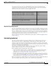
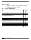
The maximum power draw of the Cisco ASR 903 Router chassis and its configurable hardware
components are listed in the following table. The maximum power draw values are not affected by
whether the router chassis contains 1 or 2 power supplies AC or DC.
Electrical Circuit Requirements
Each Cisco ASR 903 Router requires a dedicated electrical circuit. If you equip it with dual power feeds,
provide a separate circuit for each power supply to avoid compromising the power redundancy feature.
The Cisco ASR 903 Routers can be powered by a DC source or an AC source. Ensure that equipment
grounding is present and observe the power strip ratings. Make sure that the total ampere rating of all
products plugged into the power strip does not exceed 80% of the rating.
For more information about the Cisco ASR 903 Router power supply, see the “Power Supply Features”
section on page 1-3.
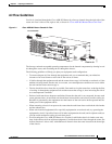
Site Cabling Guidelines
This section contains guidelines for wiring and cabling at your site. When preparing your site for
network connections to the Cisco ASR 903 Router, consider the type of cable required for each
component, and the cable limitations. Consider the distance limitations for signaling, electromagnetic
interference (EMI), and connector compatibility. Possible cable types are fiber, thick or thin coaxial, foil
twisted-pair, or unshielded twisted-pair cabling.
Also consider any additional interface equipment you need, such as transceivers, hubs, switches,
modems, channel service units (CSU), or data service units (DSU).
Before you begin, read these important notes about cabling:
• The T1/E1 interface module for the Cisco ASR 903 Router uses a high-density connector that
requires the use of a T1/E1 interface cable and a customer-provided patch panel. For more
information, see “Connecting T1/E1 cables” section on page 3-40.
• Shielded cables must be used to connect to the DB-25 alarm connector on the fan tray in order to
comply with FCC/EN55022/CISPR22 Class A emissions requirements. For information about the
fan tray alarm port, see “Connecting the Fan Tray Alarm Port” section on page 3-42.
Before you install the Cisco ASR 903 Router, have all the additional external equipment and cables on
hand. For information about ordering, contact a Cisco customer service representative.
Hardware component(s) Maximum power draw value
Router chassis with 2 power supplies, 1 fan tray, and 1 RSP1A 195 W
Router chassis with 2 power supplies, 1 fan tray, and 1 RSP1B 210 W
A900-RSP1A-55 (standby) 100 W
A900-RSP1B-55 (standby) 100 W
A900-IMA1X (1-port 10 GE XFP interface module) 13.0 W
A900-IMA8T (8-port 1 GE RJ45 interface module) 17.5 W
A900-IMA8S (8-port 1 GE SFP interface module) 17.5 W
A900-IMA16D (16-port T1/E1 interface module) 14.5 W
A900-IMA4OS (4-Port OC3 interface Module) 26 W