


5-7
Cisco ASR 903 Router Hardware Installation Guide
OL-25178-04
Chapter 5 Troubleshooting
LED Summary
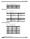
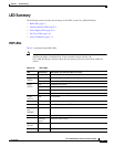
LED Summary
The following sections describe the meanings of the LEDs on the Cisco ASR 903 Router.
• RSP LEDs, page 5-7
• Interface Module LEDs, page 5-8
• Power Supply LEDs, page 5-10
• Fan Tray LEDs, page 5-10
• Alarm Conditions, page 5-11
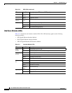
RSP LEDs
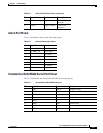
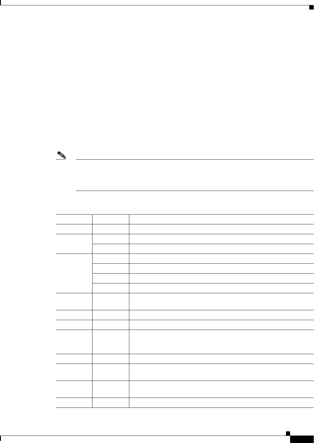
Table 5-10 summarizes the RSP LEDs.
Note A major alarm condition indicates the failure of a single fan in the fan tray; a critical alarm
indicates the failure of multiple fans. In the event that a single fan fails, the
Cisco ASR 903 Router software adjusts the fan speed to prevent excessive heat within the
chassis.
Table 5-10 RSP LEDs
LED Color/State Description (two LEDs for eachT1/E1 port)
Power
(PWR)
Off Disabled/no power to RSP
Green Power rails on RSP in range
Status
(STAT)
Off Disabled/power down
Red Failure to boot (lit at reset)
Yellow Rommon booted
Green IOS booted and running
Active
(ACTV)
Off Not available
Yellow Standby (indicates standby RSP)
Green Active (indicates active RSP)
Management
port
(MGMT)
Off No connection
Green Connected with no activity
Flashing
green
Connected with activity
Sync status
(SYNC)
Off Not enabled
Yellow Free run