


5-8
Cisco ASR 903 Router Hardware Installation Guide
OL-25178-04
Chapter 5 Troubleshooting
LED Summary
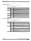
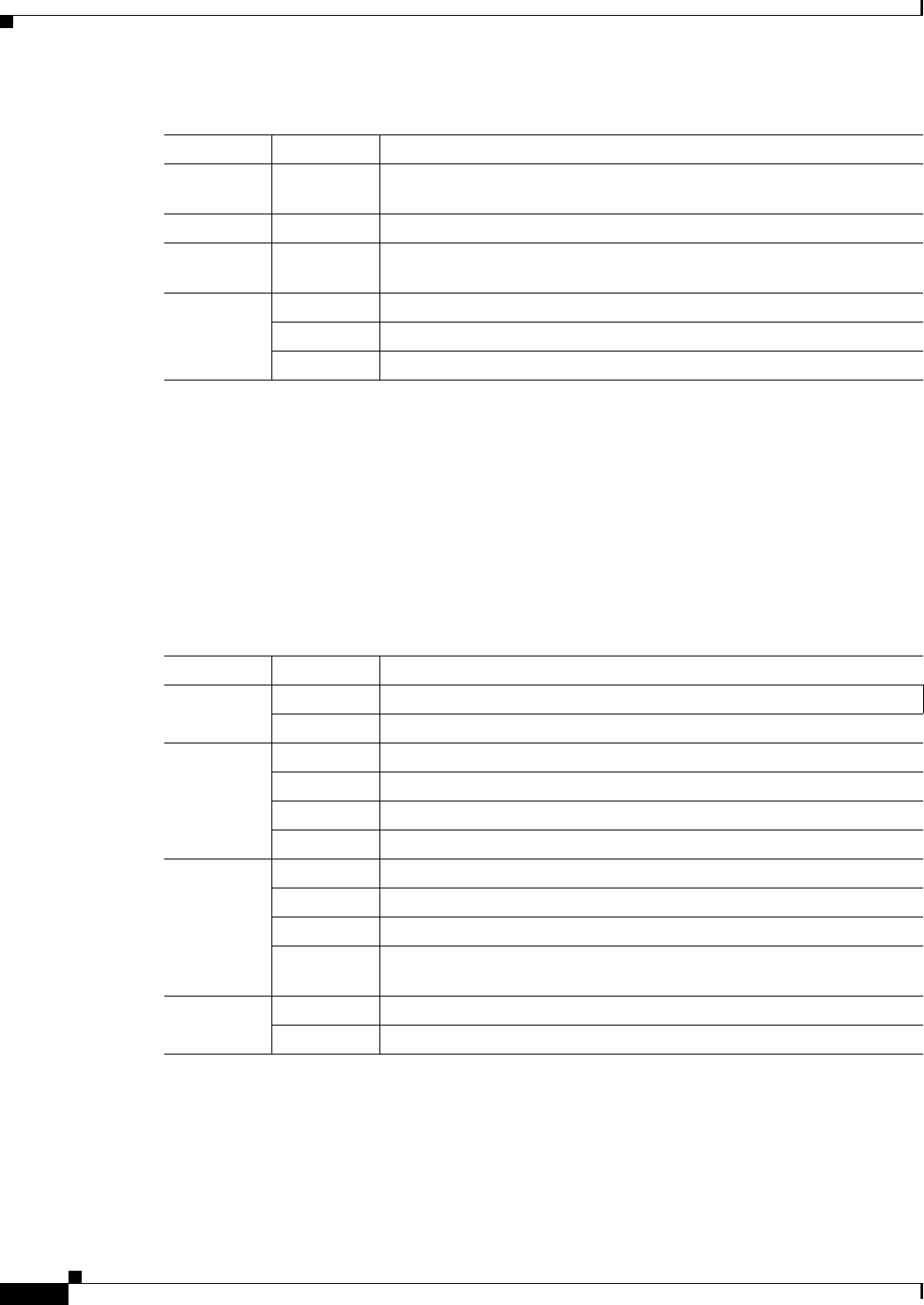
Interface Module LEDs
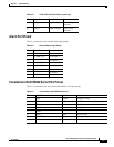
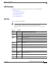
Table 5-11 summarizes the interface module LEDs. This LED summary applies to the following
interface modules:
• SFP Gigabit Ethernet Interface Module
• RJ45 Gigabit Ethernet Interface Module
• XFP 10 Gigabit Ethernet XFP Interface Module
Flashing
yellow
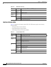
Holdover
Green Locked to source
USB flash
(MEM)
Flashing
green
USB activity
BITS Off Out of service/not configured
Amber Fault or loop condition
Green In frame/working properly
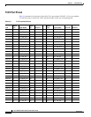
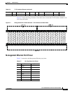
Table 5-10 RSP LEDs (continued)
LED Color/State Description (two LEDs for eachT1/E1 port)
Table 5-11 Interface Module LEDs
LED Color/State Description
Power
(PWR)
Off Disabled/no power to IM
Green Enabled and power rails on IM in range
Status
(STAT)
Off Disabled/power-down
Red Failure (on at reset)
Amber Booting (if local CPU)
Green Operational
Link status
(L)
Off Inactive or no connection
Amber Fault/loop condition
Green Ok with no activity
Flashing
green
OK with activity
Speed (S) Off 100/10 Mbps/Slow
Green 1Gbps/Full