


3-11
Cisco ASR 903 Router Hardware Installation Guide
OL-25178-04
Chapter 3 Installing the Cisco ASR 903 Router
RSP Installation
Installing an RSP Module
To install an RSP module in the router chassis, perform the following steps:
Step 1 Choose a slot for the module. Make sure that there is enough clearance to accommodate any equipment
that will be connected to the ports on the module. If a blank module filler plate is installed in the slot in
which you plan to install the module, remove the plate by removing its 2 Phillips pan-head screws.
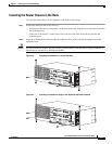
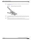
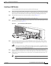
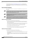
Step 2 Fully open both the ejector levers on the new module, as shown in Figure 3-14.
Caution To prevent ESD damage, handle modules by carrier edges only.
Step 3 Position the module in the slot. Make sure that you align the sides of the module with the guides on each
side of the slot, as shown in Figure 3-14.
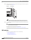
Figure 3-14 Cisco ASR 903 Router RSP Installation
Step 4
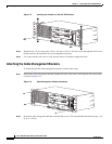
Carefully slide the module into the slot until the EMI gasket on the module makes contact with the
module in the adjacent slot and both the ejector levers have closed to approximately 45 degrees with
respect to the module faceplate.
Caution If the top slot already has an RSP module installed, and you install a second RSP module in
the slot below it, be careful not to damage the EMI gasket of the bottom RSP module against
the ejector levers of the top RSP during insertion.
Step 5 While pressing down, simultaneously close both the ejector levers to fully seat the module in the
backplane connector. The ejector levers are fully closed when they are flush with the module faceplate.
Step 6 Tighten the two captive installation screws on the module. The recommended maximum torque is 5.5
in.-lb (.62 N-m).
Note Make sure that the ejector levers are fully closed before tightening the captive installation
screws.
INPUT
OK
OUTPUT
FAIL
24V—60V 28A
INPUT
OK
OUTPUT
FAI L
24V—60V 28A
GE-0
GE-1 GE-2
GE-3 GE-4 GE-5
GE-6
GE-7
PWR
STAT
GE-0 GE-1 GE-2 GE-3 GE-4 GE-5 GE-6
GE-7
PWR
STAT
GE-0 GE-1 GE-2 GE-3 GE-4 GE-5 GE-6 GE-7
PWR
STAT
GE-0 GE-1 GE-2 GE-3 GE-4 GE-5 GE-6 GE-7
PWR
STAT
GE-0 GE-1 GE-2 GE-3 GE-4 GE-5 GE-6 GE-7
PWR
STAT
GE-0 GE-1 GE-2 GE-3 GE-4 GE-5 GE-6 GE-7
PWR
STAT
ALARM
FAN TEMP
CRIT MAJ MIN
281932
RUDY RSP
MEM TOD BITS
MGMT
ENET
1PPS
IN
1PPS
OUT
1OMHZ
OUT
1OMHZ
IN
CONSOLE
SYNC
ACT
PWR
STAT