


3-23
Cisco ASR 903 Router Hardware Installation Guide
OL-25178-04
Chapter 3 Installing the Cisco ASR 903 Router
Installing the Power Supply
Caution Secure the wires coming in from the terminal block plug so that they cannot be disturbed by
casual contact.
Step 7 Ensure that the terminal block plug is fully seated in the terminal block header on the DC power supply
panel. The plug has a locking feature. You should hear a snap or click when it is installed properly.
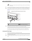
Step 8 Use a tie wrap to secure the wires to the rack, so that the wires are not pulled from the terminal block
plug by casual contact. Make sure the tie wrap allows for some slack in the ground wire, as shown in
Figure 3-20.
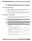
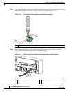
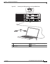
Figure 3-20 Complete DC Terminal Block Plug Insertion and Secure Tie Wrap
Step 9
Use a tie wrap to secure the wires to the handle. Leave a service loop on the ground wire between the
handle and the connector such that it is the last to receive strain if the wires are pulled.
This completes the procedure for connecting the DC power supply in the Cisco ASR 903 Router.
If you are installing a redundant DC power supply, repeat these steps for the second power source.
Activating the DC Power Supply
Perform the following procedure to activate the DC power supply:
Step 1 Remove the tape from the circuit-breaker switch handle, and restore power by moving the circuit-breaker
switch handle to the On (|) position.
Step 2 Verify power supply operation by checking if the power supply front panel LEDs are in the following
states:
1 Lead wires secured with a tie wrap 2 DC power supply terminal block plug being
inserted into terminal block header.
INPUT
OK
OUTPUT
FAIL
24V—60V
28A
INPUT
OK
OUTPUT
FAIL
24V—60V 28A
RUDY RSP
MEM TOD BITS MGMT
ENET
1PPS
IN
1PPS
OUT
1OMHZ
OUT
1OMHZ
IN
CONSOLE
SYNC
ACT
PWR
STAT
255731
ALARM
FAN TEMP
CRIT MAJ MIN
1
2