


3-24
Cisco ASR 903 Router Hardware Installation Guide
OL-25178-04
Chapter 3 Installing the Cisco ASR 903 Router
Installing the Power Supply
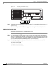
• INPUT OK LED is green
• OUTPUT FAIL LED is green
If the LEDs indicate a power problem, see Chapter 5, “Troubleshooting.”
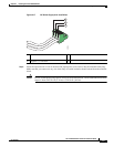
If you are installing a redundant DC power supply, ensure that each power supply is connected to a
separate power source in order to prevent power loss in the event of a power failure.
If you are installing a redundant DC power supply, repeat these steps for the second power source.
Removing and Replacing the DC Power Supply
This section provides information about removing and replacing the DC power supply in the
Cisco ASR 903 Router.
Note The Cisco ASR 903 Router power supplies are hot-swappable. If you have installed redundant power
supply modules, you can replace a single power supply without interrupting power to the router.
Caution To avoid erroneous failure messages, allow at least 2 minutes for the system to reinitialize after a power
supply has been removed or replaced.
Warning
When you install the unit, the ground connection must always be made first and disconnected last.
Statement 1046
Warning
Before performing any of the following procedures, ensure that power is removed from the DC circuit.
Statement 1003
Warning
Only trained and qualified personnel should be allowed to install, replace, or service this equipment.
Statement 1030
Warning
Installation of the equipment must comply with local and national electrical codes.
Statement 1074
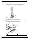
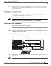
Follow these steps to remove and replace the DC power supply on the Cisco ASR 903 Router:
Step 1 Before servicing the power supply, switch off the circuit breaker in your equipment area. As an
additional precaution, tape the circuit-breaker switch in the Off position.
Step 2 Slip on the ESD-preventive wrist strap that was included in the accessory kit.
Step 3 Switch the power supply circuit-breaker switch to the Off (O) position.
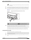
Step 4 Pull the terminal block plug connector out of the terminal block head in the power supply.
Step 5 Loosen the captive screws on the DC power supply.
Step 6 Grasping the power supply handle with one hand, pull the power supply out from the chassis while
supporting it with the other hand.