


3-25
Cisco ASR 903 Router Hardware Installation Guide
OL-25178-04
Chapter 3 Installing the Cisco ASR 903 Router
Installing the Power Supply
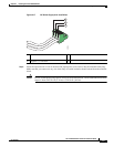
Step 7 Replace the DC power supply within 5 minutes. If the power supply bay is to remain empty, install a
blank filler plate (Cisco part number A900-PWR-BLANK) over the opening, and secure it with the
captive installation screws.
Installing the AC power Supply
The following sections describe how to install a AC power supply in the Cisco ASR 903 Router:
• Installing the AC Power Supply Module, page 3-25
• Activating the AC Power Supply, page 3-26
Warning
This product requires short-circuit (over current) protection, to be provided as part of the building
installation. Install only in accordance with national and local wiring regulations.
Installing the AC Power Supply Module
Follow these steps to install the power supply module:
Step 1 Ensure that the system (earth) ground connection has been made. For ground connection installation
instructions, see the “Installing the Chassis Ground Connection” section on page 3-5.
Step 2 If necessary, remove the blank power supply filler plate from the chassis power supply bay opening by
loosening the captive installation screws.
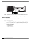
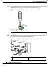
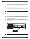
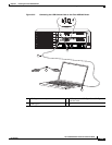
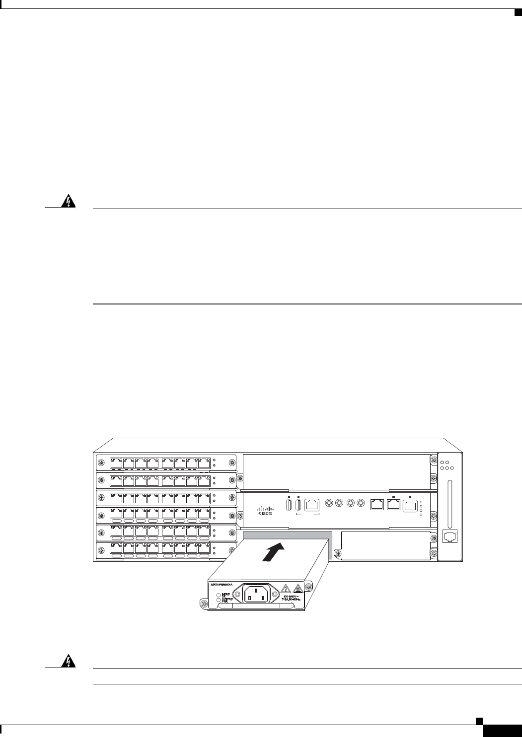
Step 3 Grasp the power supply handle with one hand. Place your other hand underneath the power supply, as
shown in Figure 3-21. Slide the power supply into the power supply bay. Make sure that the power
supply is fully seated in the bay.
Figure 3-21 Installing the AC Power Supply
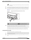
Step 4
Tighten the captive installation screws of the power supply. The recommended maximum torque is 5.5
in.-lb (.62 N-m).
Warning
Power supply captive installation screws must be tight to ensure protective grounding continuity.
GE-0 GE-1 GE-2 GE-3 GE-4 GE-5 GE-6 GE-7
PWR
STAT
GE-0 GE-1 GE-2 GE-3 GE-4 GE-5 GE-6 GE-7
PWR
STAT
GE-0 GE-1 GE-2 GE-3 GE-4 GE-5 GE-6 GE-7
PWR
STAT
PWR
STAT
L 0 S L 1 S L 2 S L 3 S L 4 S L 5 S L 6 S L 7 S
PWR
STAT
L 0 S L 1 S L 2 S L 3 S L 4 S L 5 S L 6 S L 7 S
PWR
STAT
L 0 S L 1 S L 2 S L 3 S L 4 S L 5 S L 6 S L 7 S
344750
RUDY RSP
MEM TOD BITS MGMT
ENET
1PPS
IN
1PPS
OUT
1OMHZ
OUT
1OMHZ
IN
CONSOLE
SYNC
ACT
PWR
STAT
ALARM
FAN TEMP
CRIT MAJ MIN